Industrial Jib Arm Camber Design Guide for Buyers
Most Important Takeaway
Camber design in an industrial jib arm is not about “bending the beam upward” for appearance—it is a controlled structural compensation method used to counteract -world deflection under load. A properly designed camber improves positioning accuracy, reduces tip drift, and ensures consistent load handling across the full working radius of the jib crane.
- Camber directly affects end-effector positioning accuracy under rated load
- Proper camber reduces jib arm tip deflection and swing drift
- Over-cambering can cause uneven trolley travel and stress concentration
- Under-cambering leads to excessive downward deflection and positioning error
- Camber design must match working radius, rated capacity, and duty class (A3–A5/A6)
- Structural stiffness, material grade, and weld sequence all influence camber stability
- Verification requires load test deflection data, not just theoretical calculation
Buyer Questions This Guide Solves for Cantilever Jib Crane Camber and Deflection
In cantilever jib crane procurement, buyers usually don't start with formulas. They start with practical questions like "will it drift?" or "can I place the load exactly where I need it?"
For 0.5–5 ton jib crane systems, camber and deflection behavior directly affect daily operation in assembly, machining support, and general material handling. This section summarizes the questions buyers ask before purchase.
In a cantilever jib crane system, camber directly affects how the load behaves when lifted. The beam is slightly pre-curved so that under load it becomes closer to level.
In operation:
- Without camber → visible hook drop at outreach
- With camber → more stable positioning during lifting
- Better control in assembly and machining applications
In workshop terms: "it helps the load land closer to where you expect it."
Acceptable deflection in a jib crane cantilever arm depends on application type and working radius.
In practice:
- Precision assembly → very low deflection requirement
- General workshop use → moderate deflection acceptable
- Heavy handling → focus more on safety than fine positioning
In simple terms: "the tighter the job, the lower the deflection you should allow."
In cantilever jib crane evaluation, camber should always be supported by measurable data, not only drawings.
Check the following:
- Full-load deflection test report at maximum outreach
- Load–deflection curve from manufacturer
- Clear camber geometry before and after loading
In workshop talk: "if there is no test data, you are only guessing the performance."
In a 0.5–5 ton cantilever jib crane system, camber does not work alone. It is directly linked to outreach length and rated load.
In behavior:
- Longer outreach → higher bending moment
- Higher load → more deflection at beam tip
- Camber → compensates expected downward movement
In simple workshop language: "farther reach plus heavier load means more sag, camber is used to balance that."
In jib crane cantilever design, camber is usually fixed during manufacturing, but in some cases small adjustments can be made during installation.
In practice:
- Fixed camber → stable, consistent production design
- Adjustable camber → used for site correction or special conditions
- Most 0.5–5 ton cranes use fixed camber design
In workshop terms: "fix it in factory if possible, adjust on site only if needed."
In cantilever jib crane operation, repeated loading cycles can slowly affect structure behavior. Camber helps distribute stress more evenly over time.
In practice:
- Reduces excessive stress concentration at beam tip
- Improves stability under repeated lifting cycles
- Helps maintain consistent positioning over long-term use
In simple terms: "better balance today means less deformation tomorrow."
Before buying a cantilever jib crane system, technical confirmation is more important than brochure specifications.
Key data to request:
- Full-load tip displacement test report
- Structural calculation sheet for jib arm
- Camber geometry diagram (no load vs loaded condition)
- Material certificates and welding procedure specification
- installation references with similar working radius
In workshop language: "don't just buy capacity, buy proven performance."
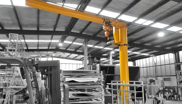
Camber Design in Industrial Jib Arms (Cantilever Jib Crane Systems 0.5–5 Ton)
In a cantilever jib crane system, camber design is a simple but practical idea. The jib arm is built with a slight upward curve before any load is applied. Then when the crane lifts a load, the beam bends down and becomes closer to level in working condition. People in workshops often just say, "it's pre-set to handle the sag." That is basically camber.
In 0.5–5 ton jib crane applications, this matters because the cantilever works like a fixed beam carrying load at the far end. Without compensation, the arm will naturally deflect under weight, especially at full outreach.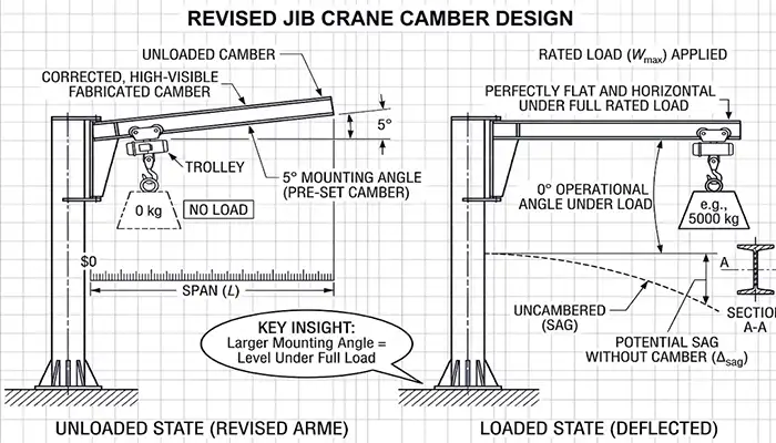
Slight upward shape built into the jib arm
Used to balance expected deflection under load
Common in workstation, rotating, and free standing jib cranes
Helps improve load positioning stability in daily use
A jib crane cantilever arm is fixed at one end and free at the other. Load is usually applied at different outreach positions, not evenly distributed.
In simple workshop terms:
Near column → stable and rigid
Far reach → more bending and movement
Full load at tip → most visible deflection
This is normal beam behavior under eccentric loading.
On paper, deflection looks controlled and predictable. In workshop use:
Movement is affected by load swing
Trolley travel adds dynamic force
Rotation introduces extra small shifts
So actual load drift in cantilever jib cranes is usually more visible during operation than in static calculation.
For industrial jib crane selection (0.5–5 ton range), camber is not just a design detail. It directly affects how stable the load feels during placement.
Without camber → more visible hook drop
With camber → smoother positioning
Poor design → more adjustment during assembly work
In use, lifting is simple. The focus is keeping the load steady at the exact position.
Camber Design in Industrial Jib Arms (Cantilever Jib Crane Systems 0.5–5 Ton)
In a cantilever jib crane system, camber design is a simple but very practical engineering idea. The jib arm is built with a slight upward curve before any load is applied. Then when the crane lifts a load, the beam bends down and becomes closer to level in working condition. In workshops people often say, "it's set a bit higher to take the sag," or "yeah, it levels out once you load it." That is basically camber in use.
In 0.5–5 ton jib crane applications, this matters because the cantilever works like a fixed beam carrying load at the far end. Without this compensation, the arm will naturally deflect under weight, especially at full outreach during daily lifting work.
Camber is basically a small intentional upward shape built into the jib arm before installation. Nothing complicated, just a controlled curve. In practice, it helps the jib arm settle into a straight working position once the load is applied.
In workshop terms:
- Slight upward curve built into the jib arm before use
- Used to balance expected deflection under working load
- Common in workstation, rotating, and free standing jib crane systems
- Helps reduce visible load drop at full outreach
Simple way to say it: no camber, you see more sag. With camber, things feel smoother during positioning. Operators usually notice it after first few lifts and say, "okay, this feels more stable."
A jib crane cantilever arm is fixed at one end and free at the other. So naturally, it behaves like a cantilever beam. This is basic structure behavior, nothing fancy.
In simple workshop understanding:
- Near the column → very stable, almost no visible movement
- Mid outreach → small but normal deflection
- Full outreach → most noticeable bending and load drift
You will often hear operators say, "near side is solid, far side moves a bit." That is just eccentric loading in lifting conditions. The farther the load goes, the more the beam reacts.
On paper, deflection is calculated in a clean and controlled way. But in industrial jib crane operation, things are not that clean. There is always a bit of movement in work.
In workshop use:
- Load swing during lifting adds small extra movement
- Trolley travel creates dynamic force on the cantilever
- Rotation (in slewing jib cranes) adds slight shift during start and stop
So in life, load drift in cantilever jib cranes shows up more during movement than during static load testing. Operators often say, "it's fine when standing still, but moving gives a bit of shift." That's normal field behavior.
For 0.5–5 ton industrial jib crane selection, camber is not just a design detail. It directly affects how stable the load feels during placement work. And in actual workshop use, that makes a big difference in daily efficiency.
- Without camber → more visible hook drop at full outreach
- With camber → smoother and more stable positioning
- Poor design → more manual adjustment during assembly or machining work
In operation, lifting is never the problem. The point is simple: keeping the load steady and placing it exactly where it should be. That's where camber design shows its value.
Camber Design Objectives in Industrial Applications
In cantilever jib crane systems, camber design is not just a drawing detail. It has clear working goals in workshop operation. In 0.5–5 ton jib crane applications, the focus is always simple: keep the load stable, reduce drift, and make positioning easier during daily lifting work.
Operators often say, "as long as it lands in the same spot, it's good." That is exactly what camber is trying to support in industrial use.
In a working cantilever jib crane, the beam always bends a little under load. No surprise here, it is normal steel behavior. Camber is used to balance this bending so the arm stays closer to level during operation.
In workshop terms:
- Load applied → beam naturally deflects downward
- Camber → pre-adjusts upward shape to offset sag
- Result → more stable hook position at full load
In practice, operators just want one thing: "don't let the hook drop too much when I lift heavy parts." Camber helps control that.
In assembly line work, especially with a 0.5–5 ton jib crane system, positioning is more important than lifting itself. If the hook does not land in the right spot, operators need extra adjustment time.
Camber helps keep this under control:
- Reduces hook drop at working radius
- Keeps placement closer to fixture point
- Improves accuracy in repetitive assembly tasks
In simple workshop language: "it lands closer where you want it." That saves time during daily production runs.
In factory operation, a cantilever jib crane is not used once or twice. It works all day, same motion, repeat again and again. This is where small deflection becomes visible.
Without camber:
- Small variation in load position between cycles
- Operator needs repeated small corrections
- Positioning consistency drops slightly over time
With camber:
- More consistent hook landing point
- Smoother repeat lifting operation
- Less "adjust and re-adjust" behavior
In workshop talk: "once set, it behaves the same every time." That's what repeatability means here.
In precision work like machining support or fine assembly, even small load drift means extra manual adjustment. Operators often say, "just a bit off, need to fix it again." That extra step costs time.
Camber design helps reduce this problem:
- Less position correction before final placement
- Faster alignment into fixtures
- More stable operation at full outreach
So in use, it's simple: less adjustment, smoother workflow, and more consistent positioning in cantilever jib crane operations.
Camber Calculation and Engineering Factors in Cantilever Jib Crane Design
In cantilever jib crane systems, camber is not decided by guessing. It is based on basic structural calculation and workshop experience. For 0.5–5 ton jib crane applications, engineers look at steel behavior, load condition, and how the jib arm will actually be used in daily lifting work.
In workshop terms, people may say, "just give it a bit more curve so it won't sag too much." But in engineering, there are several key factors behind that decision.
The first factor is the steel material itself. In most jib crane cantilever beam designs, Q235 and Q345 steel are commonly used. Each one behaves slightly differently under load.
In practical terms:
- Q235 steel → more elastic deformation under load
- Q345 steel → higher strength, lower deflection tendency
- Higher modulus → better stiffness in cantilever jib crane operation
In workshop language: "better steel, less bending." Simple but true in daily industrial use.
The second factor is the structural shape of the cantilever jib crane arm. This is where stiffness ly comes from.
Common designs include:
- I-beam jib arm → simple structure, standard deflection behavior
- Box girder jib arm → higher stiffness, better load stability
- Truss structure jib arm → lighter weight, good for longer outreach
In use, operators often feel it directly: "box girder feels more solid at full reach." That's section modulus working in practice.
In a 0.5–5 ton jib crane system, load is not always fixed. Sometimes it stays at one point, sometimes it moves along the arm. This changes deflection behavior.
Two common cases:
- Point load → maximum stress at fixed position
- Moving trolley load → changing deflection along outreach
In workshop terms: "it behaves differently when the load slides out." That's why camber is designed based on worst-case position, usually full outreach.
In cantilever jib crane engineering design, safety factor is always included. This is not only for lifting safety, but also for controlling long-term deflection.
In practice:
- Design load is higher than working load
- Extra margin added for unexpected overload
- Camber adjusted to match safe deflection range
In simple workshop talk: "we don't design it to the limit, we leave some space." That helps maintain stable performance in daily operation.
One often overlooked factor in jib crane cantilever fabrication is welding. Welding sequence affects internal stress in the beam.
In manufacturing:
- Uneven welding → residual stress builds up
- Stress release → slight beam deformation after fabrication
- Improper sequence → uneven camber shape
This is why experienced workshops control welding steps carefully. In simple terms: "weld order matters, or the beam will move later."
Types of Camber Approaches in Jib Crane Design
In cantilever jib crane systems, camber is not always done in the same way. Different factories and engineering teams choose different approaches based on load condition, outreach length, and required positioning accuracy. For 0.5–5 ton jib crane applications, the goal is always the same: reduce visible deflection and keep load placement stable in daily workshop use.
In simple workshop talk, people may say, "some cranes are bent a bit straight, some are shaped more carefully." That is basically different camber methods in practice.
Linear camber is the simplest approach used in many standard jib crane cantilever beam designs. The upward curve is made in a straight and uniform way along the span.
In practical operation:
- Simple upward adjustment along full jib arm length
- Designed for uniform load behavior
- Common in standard workstation and light-duty jib cranes
In workshop language: "just a straight, even lift in the beam." It works fine for general handling where load conditions are not very complex.
Parabolic camber is a more advanced method used in higher precision cantilever jib crane systems. The curve is not uniform. It changes along the span to match how bending actually happens under load.
In use:
- More accurate match to deflection curve
- Better performance at mid and full outreach positions
- Used in precision assembly and machining support cranes
Operators may not see it directly, but they feel it: "it stays more stable when I go far out." That's the effect of better camber matching.
Camber can be controlled in two main ways in jib crane cantilever fabrication: during factory production or after installation on site.
In practice:
- Pre-set camber → shaped during manufacturing in workshop
- Site-adjusted camber → fine tuning after installation
- Pre-set method gives more consistent results in mass production
- Site adjustment helps correct installation or foundation variation
In workshop talk: "better to get it right in the factory, but small adjustments on site are normal." Both methods are used depending on project requirements.
In modern 0.5–5 ton cantilever jib crane design, there are two main ways to control deflection: make the structure stronger or use geometric camber to balance movement.
In application:
- Reinforced stiffness → thicker section, stronger beam, less bending
- Geometric camber → controlled shape to offset expected deflection
- Often both methods are used together for better stability
In simple terms: "one makes it stronger, the other makes it smarter." Combined design gives better load stability during lifting operations.
Camber vs Deflection Control: What Buyers Must Compare
In cantilever jib crane systems, camber is only one part of the picture. The other part is actual deflection control under working load. For 0.5–5 ton jib crane applications, buyers often focus on capacity, but in daily workshop use, what ly matters is how much the jib arm moves when it is fully loaded and extended.
In simple terms, people in workshops often say, "it lifts fine, but does it stay steady when I go to the far end?" That question is exactly what camber vs deflection comparison is about.
In jib crane cantilever design standards, deflection is often controlled by span ratio limits such as L/150 or L/300. This simply defines how much the beam is allowed to bend compared to its length.
In practical use:
- L/150 → higher allowable deflection, more visible movement
- L/300 → stricter limit, better positioning stability
- Used as basic reference for 0.5–5 ton jib crane selection
In workshop language: "smaller number means stiffer crane." That's the simple way operators understand it.
A proper cantilever jib crane manufacturer should provide a load–deflection curve. This shows how the jib arm behaves under different loads and outreach positions.
In application:
- Shows deflection increase as load moves outward
- Helps identify performance at full outreach
- More useful than only rated capacity information
In simple terms: "it shows how the crane behaves, not just what it can lift." That's what buyers should look at.
There is always a difference between design data and performance in jib crane cantilever systems. Theoretical camber is calculated during design, but tested camber shows actual behavior after manufacturing.
In practice:
- Theoretical camber → calculated in engineering stage
- Tested camber → measured under load conditions
- performance may vary slightly due to fabrication and welding factors
In workshop talk: "paper looks perfect, but test tells the truth." That's why testing matters.
One of the most important checks in 0.5–5 ton cantilever jib crane evaluation is full-load tip displacement testing. This shows how much the end of the jib arm moves when fully loaded at maximum outreach.
In use:
- Measures actual hook movement under working load
- Shows worst-case positioning accuracy
- Helps determine suitability for assembly or machining work
In simple workshop terms: "this is where you see how much it ly drops when you load it fully." That data is more practical than design drawings alone.
Application-Based Camber Requirements in Cantilever Jib Crane Systems
In cantilever jib crane systems, camber requirements are not the same for every job. It depends on how the crane is used day to day. For 0.5–5 ton jib crane applications, some workshops care about millimeter-level positioning, while others care more about speed and handling efficiency.
In practical terms, people often say, "for us, accuracy matters," or "we just need it to move fast." That difference decides how camber and deflection control should be designed.
In precision assembly line cantilever jib crane systems, positioning accuracy is the main requirement. Even small load drift can affect how parts fit into fixtures.
In operation:
- Tight tolerance requirement (often ±2 mm level)
- Small deflection directly affects assembly accuracy
- Camber design must minimize visible hook drop
In workshop language: "it must land exactly where I place it." That's why higher stiffness and better camber control are needed here.
In steel fabrication yard jib crane applications, the focus is more on handling heavy parts safely and efficiently. Accuracy is important, but not extremely tight.
In practice:
- Moderate positioning tolerance is acceptable
- Load drift is less critical during placement
- Rugged structure is more important than fine accuracy
Operators usually say: "as long as it lands close, we can adjust it." So camber is used mainly for stability, not precision control.
In warehouse and logistics jib crane systems, the main goal is fast material movement. Loads are moved frequently, often with repetitive cycles.
In use:
- Speed is more important than tight accuracy
- Moderate deflection is acceptable in daily handling
- Operators focus on fast pickup and drop-off
In simple workshop talk: "just move it quickly, we don't need perfect positioning." Camber here mainly helps keep operation smooth, not ultra-precise.
In heavy-duty outdoor cantilever jib crane applications, environmental conditions become an important factor. Wind load and load sway can affect stability much more than in indoor workshops.
In operation:
- Wind introduces additional lateral force on the jib arm
- Load sway increases dynamic deflection behavior
- Camber design must consider both static and dynamic effects
In field terms: "outdoor work is never still." So the crane must handle movement, not just lifting.
Common Camber Design Mistakes in Procurement of Cantilever Jib Crane Systems
In cantilever jib crane procurement, many issues do not come from the crane itself, but from missing technical checks during purchase. For 0.5–5 ton jib crane systems, buyers often focus on tonnage and price, but ignore how the crane behaves under working load and full outreach conditions.
In workshop ity, people sometimes say, "it lifts the weight, so it should be fine." But in practice, load positioning and deflection behavior are what decide daily performance.
One common mistake in jib crane selection is focusing only on rated capacity, like 1 ton, 3 ton, or 5 ton, without checking deflection behavior.
In operation:
- Rated capacity shows lifting ability only
- Does not show cantilever bending or load drift
- Positioning accuracy can still vary under full outreach
In simple workshop talk: "it can lift, but how it lands matters more." That part is often missed during procurement.
In a cantilever jib crane system, the load is not always fixed. The trolley moves along the arm, and this changes bending behavior significantly.
In practice:
- Near column position → low bending moment
- Mid travel → moderate deflection
- Full outreach → maximum stress and load drift
Many buyers ignore this and only check "rated load at center," which does not reflect working conditions.
Another common issue in jib crane procurement is accepting equipment without proper load test or deflection test reports.
In application:
- No full-load tip displacement data provided
- No verification of cantilever deflection under rated load
- No proof of positioning performance
In simple workshop terms: "no test data means you don't ly know how it behaves." That is a risk in precision applications.
In 0.5–5 ton cantilever jib crane systems, duty class defines how often and how intensively the crane is used. This is often ignored during selection.
In practice:
- Light duty selected for high-frequency operations
- Cyclic loading not considered in design selection
- Long-term deflection and wear increases over time
In workshop talk: "it works fine at first, but after repeated use, it starts feeling loose." That is often due to wrong duty class selection.
What Buyers Should Request from Cantilever Jib Crane Manufacturers
In cantilever jib crane procurement, especially for 0.5–5 ton systems, what you ask from the manufacturer is often more important than the brochure itself. Many cranes look similar on paper, but behave differently in workshop operation.
In practice, buyers often say, "just send me the spec sheet." But for positioning accuracy and load stability, that is not enough. You need technical proof related to deflection, camber, and actual installation behavior.
This is one of the most important documents for any jib crane cantilever system. It shows how much the beam moves when fully loaded at the farthest working position.
In use:
- Measures actual tip displacement under full rated load
- Shows worst-case positioning accuracy
- More useful than capacity rating alone
In workshop language: "this tells you how much it ly drops when you push it to the end." That is what matters for operation.
A proper cantilever jib crane manufacturer should provide structural calculations for the jib arm. This includes stress, bending moment, and deflection estimates.
In practice:
- Confirms beam strength under rated load
- Shows how cantilever structure is sized
- Helps verify safety and stability design
In simple terms: "this is the math behind the crane." Without it, you are only seeing the surface.
Camber design should always be shown clearly in drawings for any jib crane cantilever system. This helps buyers understand how the beam behaves before and after loading.
In application:
- Shows upward curve before loading
- Shows expected deflection under working load
- Helps evaluate positioning behavior visually
In workshop talk: "you should see how it starts and how it ends when loaded." That makes camber design clear and predictable.
For any 0.5–5 ton cantilever jib crane, material quality and welding process directly affect long-term deflection behavior.
In practice:
- Material certificate confirms steel grade (Q235, Q345, etc.)
- Welding procedure ensures structural consistency
- Reduces risk of uneven camber or residual stress
In simple terms: "good steel and good welding keep the beam stable over time."
project references are very useful when selecting a cantilever jib crane system. They show how the crane performs in actual workshop conditions, not just on drawings.
In use:
- Shows performance in similar outreach and load conditions
- Confirms installation stability and foundation design
- Helps buyers compare -world behavior
In workshop language: "show me where you already installed something like this." That gives more confidence than any brochure.
Conclusion
Industrial jib arm camber design is a critical but often underestimated factor in crane performance. For buyers, the value is not the presence of camber itself, but whether the camber is engineered to match the actual load case, outreach length, and operational duty cycle. A well-designed camber system ensures predictable deflection behavior, stable hook positioning, and long-term structural reliability—while poor camber design leads to positioning errors, higher maintenance, and reduced operational efficiency.