Integrated Safety Logic in 25 Ton Hoist & Gantry Crane
Integrated Safety Logic in a 25 Ton Electric Hoist + Gantry Crane System
(Limit Switch, Overload Protection & Brake Coordination Guide)
Most Important Takeaway
A 25 ton electric hoist and 25 ton gantry crane system is not made safe by individual devices, but by the timed coordination between overload detection, limit switching, and electromagnetic braking, where each layer only becomes effective when it correctly interacts with the others under real dynamic load conditions.
- Safety in a 25 ton hoisting system depends on system-level interaction, not single-component protection
- Limit switches define position boundaries, but cannot control load energy
- Overload protection defines force limits, but cannot physically stop motion alone
- Electromagnetic brakes provide final motion control and load holding stability
- Fail-safe performance depends on signal priority and response timing coordination
- Improper integration increases risk of shock loading, structural fatigue, and uncontrolled drift
Questions This Guide Solves
This guide explains how overload protection, limit switches, and brake systems work together in a 25 ton electric hoist and gantry crane system, and why coordinated safety logic is critical for stable lifting operation.
In a 25 ton electric hoist and gantry crane system, these three parts do not work separately. They work together as one safety chain.
- The overload system checks if the load is too heavy (close to or over 25 ton)
- The limit switch checks if the hook or trolley has reached its travel limit
- The brake holds or stops the load when motion must stop
In simple operation:
- Load check first (overload protection)
- Position check during movement (limit switch)
- Stop and hold function (brake)
All three must match to keep lifting safe and stable.
Because each device works alone, but crane safety depends on timing between them.
For example:
- The brake may stop too fast
- The limit switch may trigger too late or too early
- The overload system may react after the load already changes
So even if every part works, the crane can still have:
- Sudden stops
- Load swing
- Extra stress on the structure
The problem is not one broken part. It is poor coordination.
Each situation has a different reaction:
Overload (too heavy load):
- The system stops lifting upward
- The brake holds the load in place
Overtravel (reaching limit position):
- The crane slows down first
- Then fully stops at the limit switch point
- The brake holds the position
Emergency stop (danger or fault):
- Power is cut off
- The brake locks immediately
- The load stays stable without moving
Brake timing is very important.
If the brake:
- Works too early → sudden stop, shock load
- Works too late → load may move or swing
- Works at the right time → smooth stop, stable load
Best case:
- Motor slows down first (VFD deceleration)
- Then brake engages
- Load stops smoothly without impact
This protects the crane structure and wire rope.
Because real crane safety is not about one part working well.
A 25 ton crane needs all systems to work together:
- Load control (overload protection)
- Position control (limit switch)
- Motion control (brake system)
If they do not work together:
- The crane may still run
- But it becomes unstable under real working load
So safety is about coordination, not individual parts.
Safety should follow a clear priority order:
- Emergency stop (highest priority, stops everything)
- Overload protection (blocks lifting if too heavy)
- Limit switch (controls travel position)
- Normal operation (only works when everything is safe)
This ensures:
- Dangerous signals always override normal operation
- The crane always moves toward a safe state
- 25 ton lifting stays controlled in real working conditions
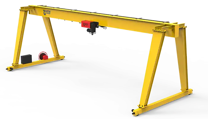 25 ton single girder gantry crane design for your reference
 System-Level Safety Concept in 25 Ton Gantry Crane Operations
System-level safety in a 25 ton gantry crane is not based on one protective device alone. It depends on how the hoist, traveling mechanism, brake system, and electrical controls work together continuously during lifting, traveling, stopping, and load changes.
In a 25 ton gantry crane system or overhead lifting setup, safety does not come from a single protection device doing its job alone. It comes from how the full system reacts as one unit when the load starts moving, stopping, or shifting under real working conditions.
The electric wire rope hoist, the gantry travel mechanism, and the electrical control system are not independent parts in practice. They operate like a connected loop. Load changes are detected, motion is adjusted, and stopping happens through a sequence rather than a single action.
In simple terms, the crane is always "talking to itself" during operation. It checks load condition, checks position, and controls motion at the same time. This is what keeps a 25 ton system stable when conditions are not perfect.
- The hoist manages lifting force and wire rope tension during load changes
- The traveling system adjusts movement to avoid side loading or uneven stress
- The control system coordinates signals between motion, load, and stopping functions
- Safety devices do not act alone; they respond based on system status, not isolated triggers
- Each action depends on timing, not just on whether a device is switched ON or OFF
In actual industrial use, a 25 ton gantry crane rarely operates under ideal conditions. Loads are not always centered. Operators do not always lift smoothly. And materials like steel plates, coils, or structural parts often create uneven force during lifting.
Because of this, safety has to respond to changing conditions in real time, not just static limits.
In workshops or steel handling yards, this becomes even more important. The crane is not only lifting weight; it is dealing with movement, swing, and sudden load changes.
- Load is often shifted slightly during lifting, creating side stress on the bridge beam
- Start and stop actions create small but repeated impact forces on the structure
- Long spans in gantry cranes increase sensitivity to uneven loading
- Repeated lifting cycles introduce fatigue that builds up over time, not instantly
- Operator behavior affects how smoothly or roughly the system transitions between states
So, safety design is not only about "stopping overload" or "stopping overtravel." It is about making sure the crane reacts in a controlled way every time the load condition changes.
A 25 ton electric hoist and gantry crane system works through continuous coordination between sensing, decision-making, and mechanical response. It is not a one-step protection process.
In practical operation, the system follows a loop like this:
- The hoist detects load condition through load sensing or motor current feedback
- The limit switch monitors hook position and travel boundaries
- The control system decides whether movement is allowed or restricted
- The brake responds to stop or hold motion when required
- The system resets into monitoring mode once the condition stabilizes
This loop runs every time the crane moves. Not just during faults, but during normal lifting as well.
This type of integrated safety logic becomes critical in real working environments where 25 ton gantry cranes are used continuously and under variable conditions.
Typical applications include steel mills, fabrication workshops, heavy equipment assembly, and material storage yards. In these environments, load behavior is not consistent, and each lift can behave differently.
- Steel plates may be lifted in bundles or single pieces, changing load distribution
- Fabricated structures often have uneven center of gravity
- Long-span gantry cranes experience higher sensitivity to load shift
- Frequent start-stop operation increases mechanical stress on braking systems
- Outdoor or semi-outdoor installations introduce additional environmental variation
In these conditions, isolated protection devices are not enough. The system has to react as a coordinated structure, otherwise small disturbances can turn into repeated mechanical stress.
In real industrial projects, engineers and buyers often focus on rated capacity first, such as "25 ton hoist" or "25 ton gantry crane." But capacity alone does not describe how the system behaves under real lifting cycles.
What actually matters is how smoothly the system handles transitions:
- When lifting starts from rest
- When load reaches mid-air and stabilizes
- When the crane stops suddenly or slowly
- When load is near maximum capacity
- When position limits are approached
Each of these moments requires the system to adjust in a controlled way. If coordination is weak, the crane may still operate, but stress on the structure and components increases over time.
In a 25 ton gantry crane system, safety is not a single protective function. It is the behavior of the whole lifting system working together under real load movement, where hoist, travel mechanism, and control logic continuously adjust to keep motion stable and controlled under changing industrial conditions.
Mechanical Limit Switch as Position Boundary Protection
Mechanical limit switches in a 25 ton gantry crane system are used for hook travel and trolley position protection. Their role is to prevent unsafe over-travel conditions and support controlled stopping through coordinated crane safety logic.
In a 25 ton electric hoist and gantry crane system, the mechanical limit switch is used as a travel limit protection device for hook lifting height and trolley running position. Its main role is to prevent the hoisting mechanism from moving beyond safe mechanical travel range during upward lifting, downward lowering, and crane trolley movement along the bridge beam.
In real industrial crane applications such as steel mill overhead crane systems, fabrication workshop gantry cranes, and heavy-duty material handling equipment, the limit switch works as a physical boundary control element inside the crane safety chain.
It does not monitor lifting capacity or load weight. Whether the system is lifting 2 tons or the full 25 ton rated load electric hoist capacity, the limit switch only reacts to position change, not force.
- Controls overhead crane hook travel limit (upper and lower limit protection)
- Protects wire rope hoist over-winding and over-lowering conditions
- Limits gantry crane trolley end travel on bridge beam rails
- Works as part of crane safety interlock system for position control
- Does not provide overload protection or load weight monitoring function
In modern 25 ton gantry crane electrical control systems, mechanical limit switches are commonly designed with a two-stage safety response to avoid sudden stopping impact and reduce structural shock load on the crane girder and hoisting mechanism.
The first stage is the pre-limit switch (slow down limit switch). When the hook or trolley approaches the boundary, the system sends a signal to reduce hoisting speed through the control panel or VFD (variable frequency drive). This is often used in low headroom electric hoist systems and European standard gantry crane configurations, where smooth deceleration is required.
The second stage is the final limit switch (emergency cut-off limit switch). Once activated, it immediately stops the upward or downward movement of the hoist or trolley to prevent over-travel of crane hook block, drum overrun, or mechanical collision with end stop structures.
- Pre-limit stage supports controlled deceleration of hoist motor speed
- Final limit stage triggers emergency stop of electric hoist lifting motion
- Reduces impact load on bridge crane end beams and trolley wheels
- Common in double girder gantry crane and single girder overhead crane systems
- Improves safety in high duty cycle industrial crane operations
A key technical point in 25 ton overhead crane safety design is that the mechanical limit switch has no function in controlling load weight or lifting force. It is only a spatial boundary protection device for crane movement range control.
This means the limit switch cannot prevent:
- Overloading of 25 ton electric wire rope hoist rated capacity
- Excessive stress on crane bridge beam structure due to dynamic load
- Wire rope fatigue caused by repeated heavy lifting cycles
- Structural deformation in gantry crane runway beam system
Because of this limitation, limit switches must always work together with:
- Load cell based overload protection system for hoist load monitoring
- Motor current based overload relay protection in crane electrical panel
- Electromagnetic brake system for hoist load holding and emergency stop
- Crane control system safety interlock logic for motion cut-off coordination
Without this coordination, even if the limit switch works correctly, the system may still experience high impact stopping force under full load 25 ton lifting conditions, especially in heavy-duty material handling environments.
In a properly designed 25 ton gantry crane integrated safety system, the mechanical limit switch is part of a coordinated safety logic chain rather than a standalone protection device.
During normal crane operation:
- Overload protection system continuously checks hoist load weight and lifting force condition
- Limit switch monitors hook travel height and trolley end position
- VFD or contactor control system manages smooth hoisting and crane travel speed control
- Electromagnetic brake system remains engaged or released depending on motion state
During upper limit approach in hoisting:
- Pre-limit switch activates first and sends slow down signal to hoist motor controller
- Final limit switch triggers hoist motor power cut-off
- Electromagnetic brake engages to prevent hook drift or load rebound
- Overload system remains active to ensure no re-lifting under unsafe condition
During emergency or fault condition:
- Limit switch supports emergency hoist travel cut-off protection
- Brake system ensures safe load holding in suspended position
- Control system prioritizes fail-safe stopping mode in crane operation safety logic
This coordination is critical in steel plant overhead crane systems, shipyard gantry cranes, and heavy industrial lifting equipment, where sudden stopping without controlled deceleration can create shock load impact on crane girder and trolley wheel assemblies.
In real working environments such as steel fabrication workshops, precast concrete yards, and heavy equipment assembly plants, mechanical limit switches operate repeatedly under high cycle crane operations.
Their role is to ensure repeatable and predictable stopping points for:
- Hook block upper limit protection during repeated lifting cycles
- Trolley travel end position control on long-span gantry cranes
- Hoist drum over-wind prevention in wire rope electric hoist systems
- Safe stopping alignment for automated or semi-automated crane operations
Although simple in structure, their reliability directly affects the long-term stability of:
- crane runway beam alignment
- hoist drum and wire rope service life
- gantry crane structural fatigue behavior
- overall industrial crane safety performance
In a 25 ton electric hoist and gantry crane system, the mechanical limit switch functions as a position boundary safety device for hook travel and trolley movement control, but its real effectiveness depends on its integration with overload protection systems, VFD controlled deceleration logic, and electromagnetic brake coordination, ensuring that crane stopping occurs in a controlled, low-impact manner rather than a sudden structural shock event under full load industrial operating conditions.
Electrical Overload Protection as Load Safety Intelligence
Electrical overload protection in a 25 ton gantry crane system provides continuous load monitoring and lifting safety control, helping the crane maintain safe operating conditions during repeated industrial lifting cycles.
In a 25 ton electric hoist and gantry crane system, the electrical overload protection function is responsible for continuous load weight monitoring and lifting force control during hoisting operations. It is a core part of the crane safety interlock system, working together with the limit switch system and electromagnetic brake to maintain safe operation under rated and dynamic loading conditions.
In modern industrial overhead crane systems, steel mill gantry cranes, and heavy-duty wire rope electric hoist applications, overload protection is not only about alarm signals. It is about controlling whether the hoist is even allowed to continue lifting under real working load conditions.
Depending on system design, overload detection is achieved through:
- Load cell based crane overload protection system (high accuracy industrial standard)
- Motor current based overload relay protection (traditional electric hoist control method)
Both methods are used in 25 ton rated capacity overhead crane systems, but load cell based monitoring is increasingly preferred in precision material handling and high duty cycle operations.
- Monitors real-time hoist load weight during lifting cycles
- Works as part of crane electrical control panel safety logic
- Supports 25 ton rated load protection with safety margin control
- Integrates with VFD crane control system or contactor-based control system
- Provides feedback for safe lifting decision and motion permission control
In a properly designed 25 ton gantry crane integrated safety system, overload protection is not a simple alarm function. It actively participates in lifting decision control and motion blocking logic.
Its operation is usually structured into three functional layers:
The first layer is overload warning at near-rated capacity condition. When the load approaches the rated limit, typically around 90–100 percent of the 25 ton capacity, the system provides an early warning signal. This is especially useful in steel plate lifting, coil handling, and heavy fabrication component lifting, where operators need real-time feedback before reaching unsafe conditions.
The second layer is lifting inhibition under overload condition. When the load exceeds the preset threshold, the system blocks further upward hoisting command. This prevents the motor from applying additional lifting force that could increase stress on the wire rope hoist drum, hook assembly, and crane bridge beam structure.
The third layer is safety interlock integration with crane control system. Once overload is detected, the system communicates with the main controller to ensure that unsafe motion commands are not executed until the load condition returns to a safe range.
- Early warning stage at near 25 ton rated load threshold condition
- Motion blocking stage preventing upward hoist motor operation under overload
- Safety interlock stage integrating with crane PLC or relay control system logic
- Protects wire rope fatigue life and hoist drum mechanical integrity
- Reduces risk of structural over-stress in gantry crane bridge beam system
In real working environments such as steel mills, fabrication workshops, precast concrete plants, and heavy equipment assembly lines, load conditions are rarely stable. The same 25 ton gantry crane may handle different load shapes, uneven centers of gravity, and shifting material stacks.
Because of this, overload protection becomes a key part of crane structural fatigue control strategy, not just a safety alarm.
Without proper overload protection coordination, repeated over-capacity or near-capacity lifting can lead to:
- Gradual fatigue accumulation in bridge crane girder steel structure
- Increased stress on end carriage wheels and runway beam rails
- Accelerated wear of wire rope electric hoist lifting mechanism
- Higher probability of shock load during lifting start and stop cycles
- Reduced service life of gantry crane mechanical components
This is especially important in high-frequency industrial lifting operations, where the crane is running continuously throughout production shifts.
In a fully integrated 25 ton electric hoist safety system, overload protection does not work alone. It is part of a coordinated response system that includes limit switch feedback and electromagnetic brake control.
During normal lifting:
- Overload system continuously checks real-time hoist load condition
- Limit switch monitors hook travel position and crane movement boundaries
- Control system allows motion only within safe load and position range
- Electromagnetic brake engages only when stopping or holding load
During overload condition:
- Overload protection immediately blocks upward hoisting command
- Electromagnetic brake holds load in stable suspended position
- Control system prevents further load increase until condition is normalized
- System avoids unnecessary mechanical stress on 25 ton hoisting mechanism
During integration with limit switch events:
- Overload system ensures lifting is already within safe range before positional cut-off occurs
- Brake system prevents load swing or rebound during sudden stopping
- Combined logic reduces impact load on gantry crane structure and hoisting assembly
This coordination is essential in heavy-duty crane applications such as steel coil handling cranes and structural fabrication gantry cranes, where both load weight and motion position must be controlled simultaneously.
In real industrial use, overload protection operates continuously in the background of every lifting cycle. Operators may only see a warning or a blocked movement, but behind this response, the system is constantly evaluating load behavior.
Its practical role includes:
- Preventing repeated lifting beyond 25 ton rated crane capacity
- Supporting safe handling of uneven steel plate or bundled material loads
- Protecting crane structure during frequent start-stop lifting operations
- Ensuring consistent performance in high duty cycle gantry crane systems
- Reducing long-term fatigue damage in hoisting and bridge crane components
Over time, this contributes directly to the stability and service life of the entire crane system, especially in continuous industrial production environments.
In a 25 ton electric hoist and gantry crane system, electrical overload protection functions as a real-time load monitoring and motion control safety layer, and its effectiveness depends on its coordination with limit switch position control and electromagnetic brake system response, ensuring that lifting operations remain within safe load boundaries while preventing structural fatigue and mechanical overload during repeated industrial crane working cycles.
Electromagnetic Brake System as Motion Control Layer
Electromagnetic brakes in a 25 ton electric hoist and gantry crane system provide load holding, motion stopping, and emergency braking control, helping maintain stable lifting performance and safe suspended load behavior during industrial crane operations.
In a 25 ton electric wire rope hoist and gantry crane system, the electromagnetic brake is a core motion control and load holding safety device integrated into the hoisting motor system. Its function is not limited to stopping the crane; it is responsible for maintaining stable load position during both normal operation and fault conditions.
In practical industrial overhead crane systems, steel workshop gantry cranes, and heavy-duty material handling equipment, the electromagnetic brake is directly connected to the safety of suspended 25 ton loads. It works together with the hoist motor, VFD control system, limit switch, and overload protection system to ensure controlled motion and stable load behavior.
The brake is typically installed on the motor shaft of the hoisting mechanism, and it operates automatically based on electrical control signals or power loss conditions.
- Controls load holding in suspended position for 25 ton electric hoist systems
- Acts as part of crane motion stopping and emergency shutdown system
- Engages automatically during power failure or control signal loss
- Works with VFD controlled deceleration in modern gantry crane systems
- Supports fail-safe braking in overhead crane safety design architecture
In a properly designed 25 ton gantry crane safety system, the electromagnetic brake is not only a stopping component. It is part of the motion stability and load control layer, ensuring that lifting operations remain stable under both normal and abnormal conditions.
The first function is load holding during power-off condition. When motor power is removed, either intentionally or due to system fault, the brake engages immediately to hold the suspended load in place. This is critical in preventing downward drift of heavy loads such as steel plates, coils, or structural components.
The second function is controlled deceleration during VFD-assisted stopping. In modern variable frequency drive (VFD) controlled overhead crane systems, braking is not purely sudden. The brake works in coordination with motor deceleration, allowing smoother stopping and reducing shock load on the crane bridge beam and hoist drum system.
The third function is prevention of uncontrolled downward motion during failure scenarios. This includes situations such as power loss, control system failure, or emergency stop activation. In these cases, the brake becomes the final mechanical barrier preventing load drop.
- Maintains stable load holding for 25 ton suspended lifting operations
- Supports controlled stopping in VFD based crane control systems
- Engages during emergency stop and electrical failure conditions
- Protects against wire rope reverse rotation and hook drop risk
- Ensures stability in gantry crane and bridge crane lifting safety systems
In real industrial environments such as steel mills, heavy fabrication workshops, precast concrete production plants, and machinery assembly facilities, the electromagnetic brake is constantly subjected to frequent engagement and release cycles.
Unlike theoretical operation, real crane usage involves:
- Frequent start-stop lifting cycles during production work
- Repeated full load or near full load lifting at 25 ton capacity range
- Sudden operator commands requiring immediate stopping response
- Variable load conditions causing different braking force demands
- Continuous operation across long working shifts
Because of this, brake performance directly affects not only safety, but also mechanical stability of the entire crane system.
If braking is not properly controlled or synchronized, it may lead to:
- Sudden shock load transfer to gantry crane bridge beam structure
- Increased wire rope tension fluctuation during stopping cycles
- Excessive wear on hoist motor shaft and brake lining system
- Load swing in long-span overhead crane applications
- Reduced service life of mechanical and structural crane components
This is especially important in large-span gantry crane systems, where even small braking irregularities can cause visible load swing due to inertia effects.
In a fully integrated 25 ton electric hoist safety logic system, the electromagnetic brake does not operate independently. It is part of a coordinated response chain together with the mechanical limit switch and electrical overload protection system.
During normal lifting:
- Brake is released only when hoist motor is energized and motion is commanded
- Overload system ensures safe lifting load condition before motion begins
- Limit switch monitors hook travel position continuously
- Brake remains ready for immediate engagement when stopping is required
During stopping or deceleration:
- VFD reduces hoist motor speed to minimize mechanical shock
- Brake engages after controlled deceleration phase
- Limit switch ensures stopping occurs within safe travel boundaries
- System avoids abrupt mechanical impact on 25 ton hoisting structure
During emergency conditions:
- Power failure triggers automatic brake engagement
- Overload and limit switch signals support fault diagnosis and safety response
- Brake becomes final holding mechanism for suspended load
- Load remains stable without uncontrolled downward movement or drift
This coordination is essential in heavy-duty gantry crane applications such as steel plate handling cranes, coil lifting systems, and large structural assembly cranes, where motion stability directly affects both safety and production efficiency.
In real-world crane operation, the electromagnetic brake is one of the most frequently used safety components in the system. Every lifting cycle involves at least one braking action, whether during stopping, holding, or emergency response.
Its practical behavior includes:
- Holding suspended loads during idle or paused crane operation
- Stabilizing load during positioning in overhead crane assembly work
- Supporting safe stopping in high-cycle industrial gantry crane systems
- Preventing drift during partial power fluctuation conditions
- Ensuring predictable stopping behavior in 25 ton electric hoist operations
Over time, brake stability directly influences operator confidence, system reliability, and overall crane safety performance in continuous production environments.
In a 25 ton electric hoist and gantry crane system, the electromagnetic brake functions as a motion control and load holding safety layer, and its performance depends heavily on coordination with limit switch position control and overload protection load monitoring, ensuring that every stopping, holding, or emergency event is managed in a controlled and stable manner without creating unnecessary dynamic impact on the crane structure or hoisting mechanism.
Integrated Safety Coordination Between Limit Switch, Overload System, and Brake
Integrated crane safety coordination ensures that limit switches, overload protection systems, and electromagnetic brakes work together as one controlled safety chain during normal lifting, overload, overtravel, and emergency conditions in 25 ton gantry crane operations.
In a 25 ton electric hoist and gantry crane system, real safety performance is defined by how the limit switch, overload protection system, and electromagnetic brake coordinate under working load conditions. These three systems do not operate as isolated safety devices. They form a connected crane safety interlock logic chain that controls load movement, stopping behavior, and fault response.
In real industrial environments such as steel workshop overhead crane systems, heavy-duty gantry crane structures, and wire rope electric hoist lifting applications, the interaction between these systems determines whether the crane stops smoothly or produces sudden mechanical impact under load.
- Limit switch handles hook travel position control and trolley boundary protection
- Overload system manages 25 ton rated load monitoring and lifting force control
- Electromagnetic brake controls load holding and motion stopping stability
- All three systems work inside a crane electrical safety control system logic loop
- System behavior depends on signal priority and timing coordination, not single-device action
During normal operation of a 25 ton gantry crane or overhead hoist system, all three safety systems remain active but operate in a coordinated monitoring state rather than triggering action.
In this stage, the overload system continuously evaluates real-time lifting load conditions, ensuring the hoist is operating within the rated capacity range. At the same time, the limit switch monitors hook height position and trolley travel movement along the bridge beam, ensuring that the crane remains within mechanical boundaries.
The electromagnetic brake remains disengaged only when motion is required, and it is prepared to engage immediately when stopping is commanded.
- Overload protection continuously checks actual hoist load weight during lifting cycle
- Limit switch tracks hook upper limit and lower limit travel position
- Brake releases only during controlled hoist motor operation and crane movement
- System maintains stable operation under 25 ton rated capacity lifting conditions
- Control system ensures smooth coordination in VFD based or contactor based crane control systems
When the system detects overload in a 25 ton electric hoist system, the safety logic shifts from monitoring mode to restriction mode. This is a critical part of crane overload protection system behavior in industrial applications.
Once the load exceeds the preset threshold, the overload system immediately blocks further upward lifting commands. This prevents additional stress on the wire rope hoist drum, hook assembly, and gantry crane bridge structure.
At the same time, the electromagnetic brake holds the load in a stable suspended position, ensuring that no unintended downward or upward movement occurs.
- Overload system blocks hoist upward motion command in real time
- Brake maintains stable suspended load holding condition under 25 ton load
- System prevents further stress on crane structural components and lifting mechanism
- Limit switch continues to monitor position but is not primary trigger in this condition
- Control system ensures safe reset before lifting can resume
This coordination ensures that overload is not just detected, but actively controlled through motion prevention and load stabilization.
In overtravel situations, such as when the hook approaches upper or lower limits in a 25 ton gantry crane system, the limit switch becomes the primary trigger in the safety chain.
The system typically uses a two-stage response. The pre-limit stage reduces hoist speed through the control system, while the final limit stage triggers immediate shutdown of motion to prevent mechanical collision or over-winding of the hoist system.
At the same time, the electromagnetic brake engages to stabilize the load and prevent rebound or swing after stopping.
- Limit switch activates slow-down and final cut-off protection sequence
- Brake engages to prevent hook collision and mechanical impact at travel end
- System transitions from motion state to load holding state safely
- Overload system continues monitoring load condition during shutdown
- Reduces impact on bridge crane end stops and trolley rail structure
This staged coordination is essential in long-span gantry crane systems, where sudden stopping can create amplified load swing and structural stress.
During emergency stop conditions in a 25 ton electric hoist system, the safety logic prioritizes immediate system stabilization. This can be triggered by operator input, power failure, or system fault detection.
Once emergency stop is activated, power to the hoist motor is removed. The electromagnetic brake engages automatically as a fail-safe mechanism to prevent uncontrolled load movement.
Even under full load conditions, the system is designed to hold the suspended 25 ton load without drift or rebound.
- Power is removed from hoist motor and crane drive system
- Electromagnetic brake engages in fail-safe load holding mode
- Load remains stable in suspended position without uncontrolled movement
- Limit switch and overload system remain active for safety status confirmation
- System ensures controlled shutdown in crane safety emergency logic sequence
This is particularly important in industrial overhead crane systems handling heavy steel materials, where sudden load drop or rebound could create serious structural and operational risks.
In real 25 ton gantry crane operation, safety failures rarely come from a single device not working. More often, issues come from poor coordination between devices or incorrect timing in response signals.
If the limit switch, overload system, and brake are not properly synchronized, the system may still function but produce:
- Sudden stopping shock under full load conditions
- Increased structural fatigue in crane bridge beam and end carriage system
- Wire rope tension spikes during abrupt deceleration
- Load swing in long-span gantry crane applications
- Reduced service life of hoist motor and brake components
This is why modern crane safety design focuses on integrated safety logic systems for 25 ton electric hoist and gantry crane equipment, rather than treating each protection device independently.
In a 25 ton electric hoist and gantry crane system, integrated safety coordination between the limit switch, overload protection system, and electromagnetic brake ensures that every operating condition—normal lifting, overload, overtravel, or emergency stop—is managed through a controlled sequence of detection, restriction, and motion stabilization, preventing uncontrolled movement of heavy loads and reducing structural stress across the entire crane system during real industrial operation.
Safety Hierarchy and Signal Priority in Gantry Crane Systems
Safety hierarchy and signal priority in a 25 ton gantry crane system ensure that emergency stop, overload protection, limit switch control, and normal operation signals react in the correct order to maintain stable and controlled crane operation under industrial working conditions.
In a 25 ton electric hoist and gantry crane system, safety behavior is not decided by a single device acting independently. It is defined by a crane electrical control system safety hierarchy, where different signals have different levels of authority.
In real industrial crane applications such as steel mill overhead crane systems, heavy fabrication gantry cranes, and wire rope electric hoist lifting systems, multiple signals can appear at the same time—load signals, position signals, and operator commands. The system must decide which signal is allowed to take control.
This is where signal priority logic in crane safety control systems becomes essential. It ensures the system always moves toward a safe state, even when multiple conditions occur together.
- Safety logic is based on signal hierarchy in crane PLC or relay control systems
- Multiple inputs include overload signals, limit switch signals, and emergency stop commands
- System behavior depends on priority ranking, not simultaneous execution
- Designed for 25 ton rated capacity overhead crane safety management
- Ensures stable operation in high duty cycle industrial lifting environments
At the top of the safety hierarchy is the emergency stop (E-stop) signal. In a 25 ton gantry crane system, this signal overrides every other control input immediately.
Once activated, all motion commands are cancelled, including hoisting, trolley travel, and crane bridge movement. The system enters a forced safety state where motion is no longer permitted until reset.
The electromagnetic brake engages as part of the fail-safe response, ensuring the suspended load remains stable.
- Emergency stop overrides all crane motion control commands
- Immediately stops hoist motor, trolley drive, and gantry travel system
- Activates fail-safe electromagnetic brake engagement
- Ensures load stability in 25 ton suspended lifting condition
- Used in operator emergency, system fault, or safety hazard conditions
In practical operation, this is the final and most direct safety action available in the crane system.
Below emergency stop is the overload protection system priority level, which is responsible for controlling lifting force in real time.
When a 25 ton electric hoist system detects that the load exceeds the safe threshold, the system does not wait for operator action. It immediately blocks upward lifting commands to prevent further load increase.
This is especially important in steel handling cranes and heavy fabrication gantry crane systems, where uneven loads or shifting center of gravity can quickly push the system beyond safe operating conditions.
- Overload protection overrides hoist lifting commands immediately
- Prevents further increase in wire rope tension and drum load stress
- Blocks motion before structural overload of bridge crane girder occurs
- Works continuously during real-time 25 ton lifting operations
- Supports safe operation in variable industrial load conditions
At this level, the crane may still hold the load, but it will not allow further lifting until conditions return to a safe range.
The mechanical limit switch system sits below overload protection but above normal control commands in the safety hierarchy. Its role is strictly related to position control within the crane travel range.
When activated, it overrides movement commands that would cause overtravel in hook lifting or trolley movement along the gantry beam.
In real overhead crane and gantry crane safety systems, this ensures that mechanical boundaries are never exceeded, even if operator input continues.
- Limit switch overrides hoist and trolley position movement commands
- Prevents hook over-winding and over-lowering conditions
- Protects end beam collision and trolley rail overrun
- Works as part of crane travel limit protection system logic
- Ensures safe positioning in 25 ton bridge crane operation cycles
Limit switch signals are position-based, meaning they react to travel limits rather than load conditions.
At the base of the hierarchy are normal operation control signals, which include operator commands for lifting, lowering, and crane travel movement.
These signals are only effective when all higher-level safety conditions are satisfied. In other words, normal operation is allowed only when the system confirms that load, position, and safety conditions are within acceptable limits.
- Normal commands control hoist lifting, lowering, and crane travel motion
- Operate only within safe load and travel boundaries defined by safety systems
- Require confirmation from overload protection and limit switch systems
- Coordinated through VFD or contactor based crane control systems
- Enable smooth operation in daily industrial 25 ton lifting tasks
This ensures that operator control is always filtered through safety logic rather than direct mechanical action.
In real industrial conditions such as steel production plants, heavy fabrication workshops, and material handling yards, multiple signals can occur at the same time. A load may be near limit, the hook may be close to travel boundary, and an operator command may still be active.
Without clear signal hierarchy, the system could respond unpredictably.
Proper signal priority ensures:
- No conflict between overload, limit switch, and operator commands
- Predictable system response during multi-condition crane operation
- Reduced risk of abrupt mechanical shock in 25 ton lifting systems
- Stable operation under high-frequency industrial crane cycles
- Controlled transition to safe state during fault conditions
This is especially important in long-span gantry crane systems, where delayed or conflicting responses can amplify mechanical stress.
In a 25 ton electric hoist and gantry crane system, safety hierarchy and signal priority define how the system responds when multiple conditions occur at the same time, ensuring that emergency stop signals take full control, overload protection blocks unsafe lifting, limit switches manage positional boundaries, and normal operation remains active only within verified safe conditions, allowing the entire crane system to consistently default to a stable and controlled mechanical state during real industrial operation.
Engineering Risks Caused by Poor Safety Integration in a 25 Ton Electric Hoist and Gantry Crane System
In a 25 ton electric hoist and gantry crane system, safety problems rarely originate from one device failing completely. In real industrial operation, the more common issue is poor coordination between the limit switch system, overload protection system, and electromagnetic brake system inside the crane electrical control architecture.
When these systems are not properly synchronized through the crane safety interlock logic, the crane may still operate, but the way it stops, holds, and reacts to load changes becomes unstable. This is where long-term damage and operational risk begin to build up.
In steel workshop overhead crane systems, heavy-duty gantry crane structures, and wire rope electric hoist applications, these coordination gaps usually appear under repeated full-load cycles rather than during a single operation.
- Safety risk is caused by system interaction failure, not only component failure
- Common in 25 ton rated capacity industrial overhead crane operations
- Appears during frequent lifting, stopping, and emergency braking cycles
- Involves mismatch between load control, position control, and braking response
- Increases risk in high duty cycle gantry crane working environments
One of the most common risks in poorly coordinated crane systems is shock loading during sudden stop conditions. This usually happens when the limit switch or control system triggers a stop without proper deceleration coordination with the VFD and electromagnetic brake.
Instead of a smooth reduction in speed, the crane stops too quickly under full or near-full load conditions. In a 25 ton hoist system, this creates a strong dynamic impact force that travels through the entire structure.
- Occurs when brake engages without controlled deceleration sequence
- Transfers sudden force into bridge crane girder and trolley structure
- Increases impact stress in end carriage and runway beam connection points
- Common in systems without proper VFD brake coordination logic
- Reduces long-term structural stability of gantry crane frame system
Another serious issue is wire rope fatigue caused by unstable load tension changes. In a 25 ton electric wire rope hoist system, the rope is designed to work under controlled tension conditions. When braking or stopping is not properly synchronized, tension can fluctuate suddenly.
This repeated fluctuation creates internal fatigue in the wire rope structure, even if the load never exceeds rated capacity.
- Caused by uncontrolled load swing and braking mismatch
- Leads to internal fatigue in steel wire rope strands and core structure
- Accelerates wear on hoist drum and rope groove system
- More severe in frequent start-stop industrial crane operations
- Often invisible until rope replacement interval becomes shorter than expected
When safety systems are not well integrated, the crane structure absorbs irregular forces instead of smooth load transfer. This leads to stress concentration in specific areas of the bridge beam and gantry frame.
In a 25 ton gantry crane system, repeated uneven stopping or load shifting creates localized stress zones that gradually affect structural integrity.
- Happens when load is not stabilized during braking or position control
- Creates uneven force distribution on bridge crane main girder structure
- Increases long-term fatigue in weld joints and beam connection points
- More noticeable in long-span gantry crane installations
- Reduces overall structural service life under continuous operation
In systems where coordination is weak, the electromagnetic brake may be forced to engage too frequently or under high-energy conditions. This leads to brake overheating and accelerated wear of brake components.
Instead of working in a controlled sequence with deceleration, the brake becomes the primary stopping device too often.
- Occurs when brake is used without proper VFD deceleration support
- Causes excessive heat buildup in brake coil and friction lining system
- Leads to faster wear of brake pads and mechanical engagement surfaces
- Reduces reliability in high-frequency 25 ton hoisting cycles
- May result in inconsistent braking response over time
Another operational risk appears during partial power failure or unstable electrical conditions. If the brake system and control logic are not properly coordinated, the load may experience slow movement or drift instead of stable holding.
In a 25 ton hoist system, even small drift under heavy load can create safety concerns and positioning errors.
- Happens when brake engagement is not synchronized with power loss detection
- Can lead to slow downward movement of suspended 25 ton load
- Affects positioning accuracy in precision material handling operations
- Increases risk in steel plate and coil storage crane systems
- Indicates weak integration between electrical control and mechanical braking system
All these risks share a common root cause. They are not the result of a single faulty component like a limit switch failure or brake defect. Instead, they come from poor interaction between safety subsystems inside the crane control system.
When overload protection, limit switches, and electromagnetic brakes are not properly coordinated through a unified safety logic design, the system may still operate, but the response becomes inconsistent under real working conditions.
- Failure is caused by lack of coordinated crane safety interlock logic
- Results from mismatch between load detection, position control, and braking timing
- Appears under real industrial 25 ton gantry crane working cycles
- Increases long-term mechanical stress rather than immediate breakdown
- Highlights importance of system-level crane safety design instead of component-level thinking
In a 25 ton electric hoist and gantry crane system, engineering risks such as shock loading, wire rope fatigue, structural stress concentration, brake overheating, and load drift are primarily caused by poor coordination between safety subsystems, where limit switches, overload protection, and electromagnetic brakes fail to operate as a synchronized control system, leading to accumulated mechanical stress and reduced operational reliability during real industrial lifting conditions.
Practical Engineering Design Considerations
In a 25 ton electric hoist and gantry crane system, practical safety design is not achieved by simply installing limit switches, overload relays, or brakes. The real requirement is how these systems are configured together inside a crane safety control architecture, especially under real working conditions such as steel handling, fabrication workshop lifting, and heavy-duty gantry crane operations.
A properly designed system focuses on progressive control, controlled deceleration, accurate load sensing, and synchronized braking response, rather than isolated protection functions.
- Safety design must follow system-level crane control integration principles
- Components must operate as part of a coordinated crane safety interlock system
- Focus is on dynamic load behavior during real 25 ton lifting cycles
- Applicable to industrial overhead crane and gantry crane working environments
- Prioritizes stable operation under repeated start-stop and full-load conditions
A reliable 25 ton electric hoist system should always use a dual-stage limit switch design for hook travel and trolley movement control. This is essential for reducing impact load and ensuring smooth stopping behavior.
The first stage acts as a slow-down limit switch, which reduces hoist speed when the hook approaches upper or lower travel boundaries. The second stage is the final cut-off limit switch, which stops motion completely to prevent mechanical collision or overtravel.
This staged structure is widely used in overhead crane systems and gantry crane long-span applications, where sudden stopping can generate significant structural stress.
- First stage enables controlled speed reduction before reaching travel limit
- Second stage ensures complete motion cut-off at final safety boundary
- Reduces impact on bridge crane end beam and trolley rail structure
- Improves stability in 25 ton wire rope hoist hook travel control
- Supports safer operation in high-frequency industrial crane cycles
For a 25 ton crane system, load accuracy is critical. A modern design should prioritize load cell-based overload protection systems instead of relying only on motor current estimation.
Load cell systems provide direct measurement of actual lifting force, which improves accuracy in situations where load distribution is uneven, such as steel plates, coils, or fabricated structures with offset centers of gravity.
This allows the crane control system to make more reliable decisions during lifting.
- Provides real-time hoist load weight measurement accuracy
- Improves safety in 25 ton rated capacity lifting operations
- Detects uneven loading in steel handling and fabrication applications
- Works as part of crane electrical control system safety logic
- Reduces risk of structural overload in gantry crane bridge system
A key design requirement in modern 25 ton gantry crane systems is variable frequency drive (VFD) controlled deceleration. This allows the hoist and trolley to slow down gradually instead of stopping abruptly.
Without controlled deceleration, braking forces are transferred directly into the crane structure, increasing shock load and fatigue stress over time.
With VFD integration, the system reduces speed before brake engagement, creating a smoother transition from motion to stop.
- Enables smooth hoist motor speed reduction before braking stage
- Reduces impact on crane bridge beam and trolley wheel assemblies
- Minimizes wire rope tension spikes during stopping cycles
- Improves comfort and control in precision lifting operations
- Essential for high duty cycle industrial crane systems
In a properly engineered 25 ton electric hoist system, the electromagnetic brake must not operate independently. It must be synchronized with motor control signals, VFD deceleration curves, and safety interlock logic.
This ensures that braking occurs at the correct timing stage, typically after controlled deceleration, rather than as an abrupt mechanical stop under full load.
Synchronization improves both safety and mechanical durability of the system.
- Ensures brake engages only after controlled deceleration phase
- Prevents sudden load impact on hoist drum and gearbox system
- Works in coordination with limit switch and overload protection signals
- Improves stability in 25 ton suspended load holding conditions
- Reduces wear on brake lining and mechanical engagement components
A complete safety design for a 25 ton gantry crane must include full system validation testing, not only individual component checks. This includes testing under real operating conditions to confirm coordination between all safety layers.
Testing should simulate both normal and abnormal scenarios to verify real system behavior.
- Rated load testing at 25 ton full capacity lifting condition
- Emergency stop testing under full load and mid-stroke motion
- Limit switch activation testing for upper and lower travel boundaries
- Overload response verification under controlled load increase conditions
- Brake holding test during power loss or fault simulation scenarios
This ensures that the crane behaves predictably in real industrial environments such as steel mills, fabrication workshops, and heavy material handling facilities.
In a 25 ton electric hoist and gantry crane system, practical engineering safety design requires integration of dual-stage limit switch protection, load cell-based overload monitoring, VFD controlled deceleration, electromagnetic brake synchronization, and full system load testing, ensuring that the entire crane operates as a coordinated safety system capable of stable performance under real industrial lifting conditions rather than relying on isolated protection components.
Conclusion
The safety of a 25 ton electric hoist and gantry crane system is defined by integration, timing, and hierarchy, not by individual protective devices. Limit switches manage position, overload systems manage force, and electromagnetic brakes manage motion—but only when they operate as a coordinated safety logic chain can the system reliably prevent failure under real industrial loading conditions.
A properly engineered system ensures that every risk scenario—overload, overtravel, or emergency shutdown—is resolved through predictable, layered responses that protect both structural integrity and operational continuity.