
Measure Workshop for Overhead Crane Quote Guide
How to Measure Workshop Dimensions for Overhead Crane Quote | Span, Height & Hook Guide
Learn how to measure workshop dimensions before requesting an overhead bridge crane quote. Understand span, building height, hook height, bay width, and runway beam location to avoid costly design mistakes and get accurate crane pricing.
Accurate workshop measurements—especially span, building height, hook height, bay width, and runway beam location—directly determine crane feasibility, lifting performance, and final installation cost. Even small errors at the measurement stage can lead to wrong crane selection, reduced lifting height, or expensive structural modifications later.
- How to correctly measure span for overhead bridge crane design
- How building height vs hook height affects usable lifting space
- How to define bay width and crane coverage area
- How to locate and plan runway beam position correctly
- What exact workshop data crane suppliers require for quotation
- How to avoid common buyer mistakes that increase installation cost
FAQ – Overhead Bridge Crane Workshop Measurement Guide
Before requesting an overhead bridge crane quotation, buyers should understand that accurate workshop measurements are essential for proper crane design, pricing, and installation planning. The following frequently asked questions explain the key dimensions, structural requirements, and layout considerations that crane suppliers typically need to evaluate before recommending a suitable overhead crane system.
A: A crane supplier needs complete workshop layout data and industrial operating requirements to prepare an accurate overhead bridge crane quotation.
When buyers search "10 ton overhead crane price for workshop" or "bridge crane quotation requirements," the expectation is usually a quick answer, but industrial engineering needs structured data.
- Span between runway beams (center-to-center)
- Workshop height from floor to lowest obstruction
- Required hook height based on industrial lifting tasks
- Bay width and actual working layout
- Runway beam position and structural condition
- Crane capacity, duty class, and working frequency
- Power supply details and workshop environment
Without these, especially in steel plants or machinery workshops, the quotation will only be a rough estimate and may change during design confirmation.
A: Workshop dimensions must be measured using structural reference points, not general building size.
In industrial searches like "how to measure workshop for overhead crane installation," mistakes usually come from using the wrong reference points.
- Span: measure from rail center to rail center
- Building height: measure from finished floor to lowest roof obstruction
- Bay width: measure actual working zones, not just building width
- Runway reference: confirm actual beam or rail position, not wall edges
This ensures the crane design matches industrial workflow in fabrication or assembly workshops.
A: Building height is the total available vertical space, while hook height is the usable lifting height under the crane.
When buyers ask "why my crane lifting height is lower than expected," the difference comes from internal crane structure.
- Building height includes full workshop vertical space
- Hook height excludes crane girder and trolley structure
- Part of height is used by hook block and hoist system
- Safety clearance reduces final usable lifting distance
- Standard cranes lose more height than low headroom designs
So two workshops with the same height can still have different lifting performance.
A: Crane span must be measured from centerline of one runway rail to centerline of the opposite rail.
In industrial queries like "correct bridge crane span measurement," the most common error is using wall-to-wall distance.
- Measure rail center to rail center
- Do not use internal wall width
- Confirm measurement at both ends if possible
- Check structural drawing if available
- Avoid estimating from building outline only
Incorrect span can cause fabrication mismatch, wheel misalignment, or installation delay in industrial projects.
A: Runway beam location is critical because it controls crane travel path, load transfer, and structural stability.
When buyers search "overhead crane runway beam installation" or "can my building support crane rails," the key issue is structural load behavior.
- Defines crane travel alignment inside workshop
- Transfers load into columns or steel structure
- Determines whether reinforcement is needed
- Affects installation accuracy and stability
- Impacts long-term wheel wear and maintenance
Incorrect layout often leads to expensive on-site modification work.
A: Yes, incorrect bay width or poorly planned workshop layout can reduce crane efficiency and limit production flow.
In industrial searches like "best crane layout for factory workshop," bay design directly affects operation efficiency.
- Uneven bays reduce crane coverage efficiency
- Wide or irregular spacing may require multiple cranes
- Poor layout increases unnecessary crane travel distance
- Material transfer between zones becomes slower
- Overall workflow becomes less balanced in production lines
Even with a correctly selected crane, poor layout planning can reduce industrial working efficiency.
Why Workshop Measurement Is the First Step in Overhead Bridge Crane Selection
An overhead bridge crane is not a standalone lifting machine that you can simply choose from a catalog. It is a workshop-integrated material handling system, and its design is directly based on the actual building conditions. That is why, in any industrial overhead crane quotation process, the first thing a crane supplier will ask is not the capacity—it is the workshop dimensions.
In industrial projects, whether it is a single girder overhead crane, a double girder bridge crane, or a low headroom overhead crane system, the starting point is always the same: how the crane fits into the workshop structure. If the measurement is wrong, the whole crane design will shift, sometimes leading to a mismatch between crane performance and actual working requirements.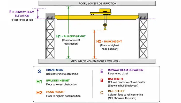
In practical terms, workshop measurement is not paperwork. It is the foundation of crane runway design, lifting height planning, and structural load calculation.
A bridge crane works as part of the building, not outside it. It runs on crane runway beams, travels across the workshop span, and lifts loads through a hoisting system that is fixed into the structural layout.
This means every overhead crane system depends on accurate industrial workshop layout data, including:
- Span between runway beam centerlines
- Workshop building height from floor to lowest obstruction
- Column spacing and bay width for crane travel coverage
- Runway beam position and structural support condition
In industrial steel structure workshops, fabrication plants, steel mills, and machinery assembly workshops, the crane becomes part of daily production flow. It is not an isolated machine. It interacts continuously with building columns, roof trusses, and working zones.
So if the workshop measurement is incorrect, even a well-designed 10 ton overhead bridge crane, 15 ton workshop crane, or heavy duty double girder crane will not perform as expected in industrial operation.
When crane manufacturers prepare an overhead crane technical proposal, they do not start from the crane model. They start from structural parameters. Each workshop dimension influences a different part of crane engineering.
In a bridge crane system, load is not carried by the crane alone. It is transferred step by step:
Hook → Hoist → Trolley → Bridge Beam → Runway Beam → Building Structure or Independent Support System
That is why accurate workshop data is required for crane structural load calculation and runway beam design.
In industrial applications:
- Incorrect column spacing affects load transfer balance
- Misjudged runway beam location leads to uneven stress distribution
- Weak building structure may require a freestanding runway crane system instead of a building-supported design
This is especially important in heavy duty overhead crane installations used in steel processing, coil handling, or machinery manufacturing workshops.
One of the most important results of workshop measurement is usable hook height calculation.
Many buyers focus only on crane capacity, such as 5 ton, 10 ton, or 20 ton overhead cranes, but overlook lifting height. In industrial reality, building height and hook height are not the same thing.
In an industrial overhead bridge crane system design, part of the vertical space is consumed by:
- Crane girder structure height
- Trolley and hoist arrangement
- Hook block assembly
- Safety clearance distance
So even if the workshop has a certain building height, the final effective lifting height (hook height under the crane) will always be lower.
This is why suppliers often ask for:
- Workshop clear height (floor to lowest obstruction)
- Required lifting height for production workflow
- Load dimensions for clearance calculation
Without this data, it is impossible to design a proper low headroom overhead crane or standard bridge crane system that fits the workshop operation.
The crane runway is the guiding track that defines how the overhead crane moves across the workshop. It is one of the most critical parts of crane installation planning and workshop layout design.
If the runway beam location is not measured correctly, several problems can occur:
- Crane travel path may not align with production zones
- Column interference may restrict crane movement
- Maintenance access space becomes too narrow
- Future workshop expansion becomes difficult
In many industrial crane installation projects, correcting runway position after installation is expensive and time-consuming. Sometimes it requires partial structural modification of the workshop frame.
That is why accurate measurement of crane runway beam centerline position and support structure type (building supported or independent gantry runway system) is essential before manufacturing begins.
In real-world crane projects, measurement mistakes do not show immediately. They appear later during installation or production use.
If workshop height or runway positioning is miscalculated, the installed crane may technically fit—but the usable lifting height becomes lower than required.
This leads to practical issues such as:
- Inability to lift materials to required stacking height
- Limited clearance for large steel structures or molds
- Slower production workflow in assembly lines
In industries like steel fabrication, machinery manufacturing, and heavy equipment workshops, even small hook height loss can affect daily efficiency.
- Over-designed crane systems increase steel structure cost and installation complexity
- Under-designed cranes reduce lifting efficiency and may not meet production requirements
For example, selecting a double girder overhead crane system when a properly designed single girder low headroom crane could have been used leads to unnecessary investment. On the other hand, underestimating workshop span or load conditions may reduce safety margin.
When industrial workshop conditions do not match submitted data, installation becomes difficult.
Common adjustments include:
- Re-positioning crane runway beams
- Strengthening building columns or adding support steel
- Modifying crane span or bridge structure on site
In industrial crane projects, these adjustments directly increase installation time and total project cost. Sometimes the crane is ready for shipment, but the workshop is not ready to receive it due to missing structural verification.
Before requesting an overhead bridge crane quotation, workshop measurement is not optional—it is the starting point of the entire engineering process.
When span, building height, bay width, and runway beam location are measured correctly, crane selection becomes straightforward and accurate. It allows the supplier to design a system that fits industrial working conditions in the workshop, not just theoretical numbers on paper.
In industrial practice, accurate workshop data always leads to better crane system design, smoother installation, and more stable long-term operation.
Crane Span-Core Design Dimension in Overhead Bridge Crane Systems
In any overhead bridge crane design, span is one of the first technical values a supplier locks into the engineering drawing. It is not just a number on paper. It directly defines how the crane bridge structure, runway beam spacing, and even fabrication limits will be designed.
In industrial workshops such as steel fabrication plants, machinery assembly workshops, steel mills, and warehouse crane systems, span determines whether the crane can move smoothly across the working area without structural conflict or unnecessary cost increase.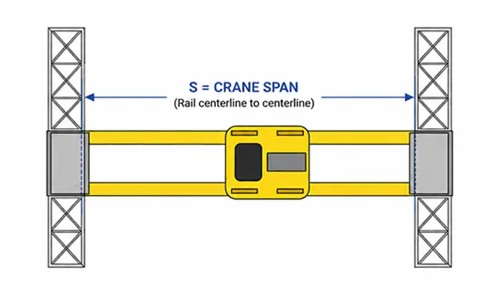
In an overhead crane system, span refers to the distance between the centerlines of the two runway beams.
In simple terms:
- Span = runway beam center to runway beam center
- It is not the wall distance
- It is not the internal clear width
This is a key point in overhead crane technical specification definition, especially for single girder overhead cranes, double girder bridge cranes, and low headroom crane systems.
In practical workshop design, the crane bridge is manufactured based on this exact span value. Even a small deviation can affect wheel alignment, beam fabrication accuracy, and installation fitment.
Accurate measurement of crane span is essential before requesting any overhead crane quotation or technical proposal.
The correct method is:
- Measure from center of one runway rail to the center of the opposite runway rail
- Confirm measurement at both ends of the workshop to avoid structural deviation
- Use structural drawing reference if available, not only field estimation
Important practical rule:
- Do not measure wall-to-wall distance
- Do not assume internal workshop width equals crane span
In many industrial crane installation projects, walls and columns do not represent the actual crane support position. The crane runs on runway beams, not on building walls.
If a workshop already has crane runway beams installed, always use the rail centerline as the reference point. This ensures the final bridge crane fabrication size matches the industrial installation condition.
Span is not just a geometric value. It affects multiple engineering decisions in the crane system.
The span defines the length of the crane main girder. A wider span requires:
- Stronger steel structure
- Higher rigidity design
- More precise fabrication control
This is especially important in heavy duty overhead crane systems used in steel plants and large fabrication workshops.
As span increases:
- Structural deflection becomes more sensitive
- Beam rigidity requirements increase
- Safety design margins must be adjusted
In industrial overhead crane applications, deflection control is not optional. It affects lifting stability, especially when handling long steel materials or heavy molds.
From a manufacturing point of view, span directly influences:
- Fabrication length of crane girders
- Welding and assembly structure
- Transport size limitations for shipping
For export projects, especially in overseas overhead crane supply, span also affects container loading planning and delivery method selection.
In many industrial project inquiries, span errors are one of the most frequent issues that lead to quotation mismatch or redesign.
This is the most common mistake.
Buyers often measure:
- Wall-to-wall distance
- Internal clear workshop width
But crane engineering requires:
- Rail center-to-center span
The difference may seem small on paper, but in industrial crane fabrication it changes:
- Wheel positioning
- Girder length
- End beam alignment
This can lead to installation misfit or on-site adjustment.
Another common issue is designing the crane only for current use.
In industrial planning:
- Workshops often expand production lines later
- Additional bays or equipment may be added
- Material flow may change over time
If span is designed without considering expansion space, the crane system may become restrictive later. In some cases, it forces partial dismantling or runway relocation during expansion.
For any overhead bridge crane quotation, span is not just a measurement—it is a core engineering parameter.
Once span is correctly defined using runway beam centerlines, the entire crane design process becomes more accurate, from structural calculation to fabrication and installation. In practical projects, correct span measurement avoids rework, reduces installation risk, and ensures the crane fits the workshop layout as intended from the beginning.
Building Height- Workshop Vertical Limitation in Overhead Bridge Crane Systems
Building height is one of the most important parameters in any overhead bridge crane installation project, but it is also one of the most commonly misunderstood. In industrial workshops, many buyers think building height is simply the roof height. In practice, it is more about the available usable vertical space for crane operation, not the architectural height of the building.
For any single girder overhead crane, double girder bridge crane, or low headroom crane system, building height directly controls whether the crane can be installed and how much lifting height can actually be achieved.
In overhead crane engineering, building height refers to the distance from the finished floor level (FFL) to the lowest structural obstruction inside the workshop.
This means the measurement must consider:
- Roof beams or steel trusses
- Hanging lighting systems
- Ventilation ducts or pipelines
- Any fixed overhead structures inside the workshop
In industrial crane design projects, engineers do not use architectural building height. They use the lowest clearance point, because the crane bridge and trolley must operate safely below all obstructions.
So in practical terms:
- Building height = usable vertical space for crane system
- Not the external building height
- Not the roof peak height
This distinction is very important when selecting overhead crane systems for low clearance workshops or steel structure plants.
To ensure accurate crane design and quotation, building height must be measured in a practical way, not estimated.
The correct method is:
- Measure from finished floor level (FFL) directly upward
- Identify the lowest fixed obstruction point inside the workshop
- Record the vertical distance between these two points
In industrial projects, this measurement should also include:
- Future flooring adjustments (if concrete leveling or coating is planned)
- Crane clearance space above the load
- Safety margin for lifting operation and hook movement
A practical rule used in overhead bridge crane design:
- Never assume ceiling height equals usable crane height
- Always measure the lowest limiting point inside the workshop structure
This ensures the final crane system can operate without interference during industrial production work.
Building height is one of the key factors that determines whether a crane system is feasible or not, especially in industrial workshop crane applications.
If building height is too low, a standard crane may not fit at all.
In this case, engineers must evaluate:
- Whether a low headroom overhead crane system is required
- Whether runway beams need to be repositioned
- Whether structural modification is necessary
In many industrial factory projects, building height is the first limiting factor that affects crane type selection.
Building height directly influences whether a workshop can use a:
- Standard overhead bridge crane system
- Or a low headroom single girder crane / compact double girder crane system
In practical terms:
- Higher building height → more flexibility in crane configuration
- Limited building height → need optimized trolley and beam design
Low headroom cranes are often used in older workshops, steel structure plants, and retrofit crane installation projects, where building height cannot be changed.
Even when a crane is installed successfully, building height still controls the final usable hook height.
If building height is limited:
- Lifting height becomes reduced
- Stack height of materials is restricted
- Production handling efficiency may be affected
That is why building height and hook height must always be analyzed together in overhead crane technical design.
In industrial environments, building height is not only about measurement—it is also about identifying physical obstacles that affect crane operation.
Steel roof trusses are one of the most common limiting factors.
They may:
- Reduce available hook travel space
- Restrict crane trolley height design
- Require low headroom crane configuration
In many steel structure workshops, truss design is fixed and cannot be modified, so crane design must adapt to it.
Industrial lighting is often installed below roof level.
If not considered:
- Lights may interfere with crane movement
- Maintenance access may be blocked
- Risk of collision with crane bridge or hook system increases
In industrial crane projects, lighting layout should always be checked before final crane design approval.
Many workshops install:
- Air ducts
- Dust collection pipelines
- Fire protection systems
These systems often occupy valuable overhead space.
If ignored during measurement:
- Crane installation height may be reduced unexpectedly
- Maintenance clearance may become insufficient
- Relocation of pipelines may be required after crane installation
This is a common issue in modern industrial workshop crane retrofitting projects.
Building height is not just a structural number—it defines the industrial working space of an overhead bridge crane system.
Once the lowest obstruction point is correctly measured and understood, crane suppliers can design a system that fits both installation conditions and production requirements. In industrial projects, accurate building height data prevents design conflicts and ensures the crane delivers the expected lifting performance inside the workshop.
Hook Height - Lifting Performance Indicator in Overhead Bridge Crane Systems
Hook height is one of the most practical and "on-site visible" performance indicators in any overhead bridge crane system design. In industrial workshops, whether it is a single girder overhead crane, double girder bridge crane, or low headroom overhead crane, what operators actually feel every day is not the crane capacity, but how high the hook can lift the load.
This is why hook height becomes a key factor in crane selection, workshop layout planning, and production efficiency evaluation.
Many crane buyers assume building height and hook height are the same thing. In industrial engineering terms, they are completely different.
- Building height = total available vertical space inside the workshop (floor to lowest obstruction)
- Hook height = actual usable lifting distance from floor to the hook in its highest working position
In practical industrial crane installation projects, building height is only the starting point. Hook height is what determines whether a load can actually be lifted, moved, and stacked efficiently.
A simple way to understand it:
- Building height is the space you have
- Hook height is the space you can industrially use
Between these two, there is always a loss caused by crane structure, including:
- Main girder height
- Trolley and hoist arrangement
- Hook block size
- Safety clearance requirement
This is why two workshops with the same building height may still have different industrial lifting performance depending on crane design.
To correctly define hook height requirement in a crane quotation or technical proposal, it must be based on industrial operation, not estimation.
The calculation usually includes three practical parts:
This refers to the maximum height of the material being handled.
In industrial applications, this may include:
- Steel coils in steel processing workshops
- Large molds in injection or stamping plants
- Machinery components in assembly workshops
- Fabricated steel structures in construction yards
If load height is underestimated, the crane may not be able to lift materials safely above surrounding obstacles.
This is the working space required above and around the load during lifting.
It includes:
- Space needed to avoid collision with floor equipment
- Clearance for safe load movement
- Space for operator visibility and control
In industrial crane practice, insufficient clearance often leads to slow operation or restricted lifting paths.
A safety margin is always included in overhead crane system design to ensure stable and safe operation.
This margin depends on:
- Type of material being lifted
- Workshop working environment
- Precision of lifting requirement
- Industry safety standards
In heavy industrial workshops, such as steel mills or fabrication plants, the margin is often higher due to larger and heavier loads.
In industrial quotation discussions, hook height is one of the most frequently misunderstood parameters in overhead bridge crane selection.
A common assumption is that:
- Higher tonnage means higher lifting height
But in industrial reality:
- Crane capacity (tons) = weight handling ability
- Hook height (meters) = vertical lifting distance
These two are completely independent design parameters.
For example:
- A 10 ton overhead crane and a 5 ton overhead crane may have similar hook height if the structure is the same
- A higher capacity crane may even have slightly reduced hook height due to stronger structural components
In a standard overhead bridge crane system, part of the vertical space is occupied by:
- Traditional trolley structure
- Standard hoist arrangement
- Higher main girder profile
This reduces the effective lifting height under the hook.
In low clearance workshops, this becomes more obvious. That is why low headroom overhead crane systems are often used when building height is limited.
These systems are designed to:
- Reduce structural height loss
- Increase effective hook travel distance
- Improve lifting efficiency in tight workshops
Hook height is not only a performance figure. It directly influences how the entire crane system is designed and selected.
In daily industrial use, hook height affects:
- How high materials can be stacked
- Whether large equipment can be assembled vertically
- How smoothly materials move between production stages
In industrial steel structure workshops and machinery assembly lines, insufficient hook height often slows down workflow more than insufficient crane capacity.
Hook height requirement often decides the crane configuration.
- If sufficient building height is available → standard overhead bridge crane can be used
- If building height is limited → low headroom crane or optimized double girder design is required
In many retrofit crane installation projects, hook height is the key reason engineers switch from a standard crane to a compact crane design.
Hook height is the industrial working performance of an overhead bridge crane system, not just a technical number in a quotation sheet.
Once load height, clearance requirement, and safety margin are correctly defined, suppliers can design a crane system that matches actual workshop operation. In industrial projects, accurate hook height planning ensures smoother production flow, better space utilization, and fewer limitations during daily lifting work.
Bay Width -Operational Coverage and Workflow Layout in Overhead Bridge Crane Systems
Bay width is often underestimated in early overhead bridge crane planning, but in industrial workshops it plays a direct role in how efficiently materials move between production areas. Whether the facility uses a single girder overhead crane, double girder bridge crane, or multiple crane systems across different bays, bay width defines the actual working coverage and how smoothly the workflow is organized.
In practical terms, crane selection is not only about lifting capacity or span. It is also about how the crane serves different production zones inside the workshop.
In overhead crane layout planning, bay width refers to the distance between structural columns or defined working bays inside a workshop.
It is a practical layout parameter used in industrial building design and crane system integration, especially in:
- Steel fabrication workshops
- Machinery assembly plants
- Warehousing and logistics facilities
- Precast concrete production areas
Bay width helps define how the workshop is divided into working sections. Each bay can represent:
- A production line
- A material storage zone
- A machining or assembly area
In industrial overhead crane system design, bay width is not just a civil structure measurement. It becomes part of the crane working logic.
Accurate bay width measurement is important for defining crane coverage and operational planning.
There are two common and acceptable methods used in industrial crane layout design:
This is the most commonly used method in engineering drawings.
- Measure from the center of one structural column to the center of the next column
- Ensures consistency with building structural grid design
- Commonly used in steel structure workshop planning and crane runway alignment
This method is preferred when designing bridge crane runway systems, because crane load is ultimately transferred through the column grid.
In some workshops, especially older facilities, engineers also consider:
- Clear working distance between obstacles
- Space available for material movement
- Actual usable production area inside the bay
This method is often used in retrofitting overhead crane systems, where structural drawings may not fully reflect industrial site conditions.
In practice, both values are often compared to understand industrial working constraints.
Bay width is not just a layout reference. It directly influences how the crane system is planned and used in daily operations.
Each bay acts as a defined working area. Bay width helps define:
- Where lifting operations take place
- How materials are transferred between zones
- The effective coverage area of each crane system
In industrial production workshops, this directly affects workflow efficiency and material flow direction.
Bay width often determines whether one crane is enough or multiple cranes are required.
For example:
- Narrow and continuous bays may be covered by a single travelling bridge crane
- Wide or separated bays may require multiple overhead crane systems
- Independent production lines often need dedicated cranes per bay
In large steel processing plants or fabrication workshops, crane coverage planning is closely linked to bay structure.
If bay width is not properly considered:
- Material transfer between bays becomes slow
- Crane travel paths may overlap or interfere
- Production workflow becomes unbalanced
In practical terms, correct bay planning helps reduce unnecessary crane movement and improves daily handling efficiency.
In industrial overhead bridge crane installation projects, bay width is not always uniform or ideal. Workshops often present practical challenges.
In larger industrial facilities, it is common to have several bays with different functions.
For example:
- One bay for raw material storage
- One bay for cutting or machining
- One bay for assembly or finishing
In such cases:
- A single crane may not efficiently serve all areas
- Separate cranes or shared crane systems may be required
- Coordination between crane zones becomes important
This is especially common in steel structure fabrication workshops and machinery manufacturing plants.
Not all workshops are built with perfectly equal bay spacing.
When bay spacing is irregular:
- Crane travel distance becomes inconsistent
- Coverage zones may overlap or leave gaps
- Workflow efficiency may decrease without proper planning
In industrial engineering practice, this requires careful crane runway alignment and operational zoning design, especially for high-frequency production environments.
Bay width is not only a structural measurement—it is a workflow planning parameter in overhead bridge crane system design.
When bay spacing and working zones are clearly understood, crane suppliers can design a system that matches industrial production flow, reduces unnecessary movement, and improves material handling efficiency across the entire workshop.
Runway Beam Location -Most Critical but Often Ignored in Overhead Bridge Crane Systems-
Runway beam location is one of those details that often looks simple on paper, but in industrial overhead bridge crane installation projects it decides whether the whole system runs smoothly or becomes difficult to install and maintain. In many cases, buyers focus on crane capacity or span first, while runway beam positioning is only considered later. This usually creates problems during installation.
In practical industrial workshops, especially steel structure factories, machinery production plants, and fabrication workshops, the runway system is the industrial "foundation line" of the crane. If it is not correct, the crane cannot operate properly even if the rest of the design is accurate.
Runway beam location refers to the exact position where crane rails and runway beams are installed along the workshop structure.
In a typical overhead bridge crane system, the runway system includes:
- Crane rails (the track surface for crane wheels)
- Runway beams (supporting steel structure)
- Column or bracket supports (load transfer points)
This system defines how the crane moves along the workshop length.
In industrial engineering terms, runway beam location is not only about "where to place the beam." It defines:
- The crane travel path
- The load transfer line into the building
- The overall alignment of the crane system
That is why in industrial overhead crane design, runway positioning is treated as a structural engineering decision, not just an installation detail.
To design a correct overhead crane runway system, several key points must be measured and confirmed before quotation and fabrication.
This is the vertical position of the runway beam relative to the finished floor level.
It affects:
- Hook height efficiency
- Crane clearance from roof structures
- Overall lifting performance of the system
In industrial projects, incorrect elevation often leads to reduced usable lifting height or interference with roof components.
This defines the horizontal position of the runway.
It must be measured carefully because:
- It affects crane alignment with the working area
- It ensures proper load distribution into columns
- It prevents interference with wall structures or equipment
In steel workshop crane systems, this dimension is critical for maintaining safe wheel travel and stable operation.
There are generally two runway support methods in overhead bridge crane installation:
Building-supported runway system
- Crane load is transferred into existing building columns
- Common in reinforced steel structure workshops
Independent runway structure (freestanding system)
- Separate steel structure supports crane loads
- Used when building cannot carry crane loads or in expansion projects
This choice directly affects cost, design complexity, and installation time.
Runway beam location is not only a construction detail. It affects the long-term performance and safety of the crane system.
If runway beams are not properly aligned:
- Crane travel becomes uneven
- Wheel wear increases
- Structural vibration may occur during lifting
In industrial overhead crane operation, even small alignment errors can become noticeable during daily use.
Runway beams transfer crane load into the building. If the workshop structure is not originally designed for cranes:
- Column reinforcement may be required
- Additional steel support structures may be added
- Foundation load capacity must be verified
This is common in retrofitted overhead crane systems where cranes are added after building construction.
Incorrect or unclear runway positioning can lead to:
- On-site modification of steel structures
- Delays in crane installation schedule
- Additional fabrication or adjustment work
In industrial projects, runway issues are often one of the main reasons for installation delay, even when the crane itself is fully manufactured and ready for delivery.
In industrial quotation and project discussions, runway beam mistakes are very common, especially when workshop drawings are incomplete.
One of the most critical misunderstandings is assuming that:
- Any steel building can directly support an overhead crane system
In industrial reality:
- Crane loads require verified structural design
- Columns and beams must be checked for load capacity
- Reinforcement may be necessary in many workshops
Without proper evaluation, this can lead to unsafe or unstable crane operation.
Another frequent issue is late-stage planning.
In many cases:
- Workshop is already built
- Crane requirement is added later
- No reserved space for runway beams exists
This results in:
- Reduced crane performance options
- More complex installation work
- Higher modification cost
In professional overhead bridge crane project planning, runway beam position should be considered at the building design stage, not after construction.
Runway beam location is one of the most important but often overlooked parts of an overhead bridge crane system.
When runway elevation, alignment, and support structure are clearly defined at the beginning, the crane design becomes stable, installation becomes smoother, and long-term operation becomes more reliable in industrial environments.
What Information Crane Suppliers Need for Accurate Overhead Bridge Crane Quotation
In industrial overhead bridge crane quotation and technical proposal preparation, suppliers do not simply price a crane based on tonnage. A proper quotation depends on how well the workshop conditions are understood. The crane must match both the structural environment of the building and the actual working requirements in daily production.
In industrial practice, whether it is a single girder overhead crane, double girder bridge crane, or low headroom crane system, missing or unclear data will directly affect design accuracy, delivery time, and final installation result.
That is why crane suppliers always request a complete set of structural and operational information before confirming any design.
A reliable overhead bridge crane quotation is based on combined engineering and operational input. The following information is essential for correct design:
Span defines the main structural size of the crane bridge.
Suppliers need:
- Accurate center-to-center distance between runway beams
- Confirmation from structural drawings or field measurement
This data determines:
- Crane girder length
- Structural rigidity design
- Fabrication and transport planning
In industrial crane engineering, incorrect span leads to misalignment between crane wheels and runway system.
Building height defines available vertical space inside the workshop.
It is used to evaluate:
- Crane installation feasibility
- Selection between standard or low headroom crane design
- Overall lifting height limitation
In many steel structure workshops and machinery plants, roof trusses and lighting systems reduce usable height, so this measurement must be accurate.
Hook height defines industrial working lifting performance.
Suppliers need:
- Maximum required lifting height from floor to hook
- Load height and stacking requirement
- Safety clearance for lifting operation
This parameter directly affects whether production needs can be met. It is often the key factor in choosing a low headroom overhead crane system.
Bay width helps define how the workshop is divided into working zones.
Suppliers use this information to:
- Plan crane coverage area
- Determine if one crane or multiple cranes are required
- Optimize material flow between production sections
In industrial workshop layouts, bay design often decides overall crane system efficiency.
Runway information is critical for crane stability and installation.
Suppliers need:
- Beam elevation height
- Distance from wall or column to rail centerline
- Structural support type (building-supported or independent system)
- Condition of existing structure (new build or retrofit)
This determines:
- Load transfer method
- Reinforcement requirements
- Installation feasibility
In many overhead crane retrofit projects, this is the most important structural evaluation point.
This defines the basic load requirement of the system.
It is used to calculate:
- Girder structure strength
- Hoisting mechanism selection
- Wheel and rail specifications
However, in industrial engineering, capacity alone is never enough without structural context.
Duty class defines how intensively the crane will be used.
Suppliers need to know:
- Frequency of daily lifting operations
- Load cycle intensity
- Working duration per shift
In steel mills, fabrication workshops, and continuous production plants, duty level has a direct impact on crane design life and component selection.
Electrical system compatibility is necessary for proper crane configuration.
Key data includes:
- Voltage level
- Frequency (50Hz or 60Hz)
- Phase type
This ensures the crane control system and motors are correctly configured for site conditions.
Material type affects both structural and operational design.
Common handling materials include:
- Steel plates and structural sections
- Steel coils or billets
- Machinery parts and molds
- Scrap materials or bulk loads
Each material type affects:
- Lifting method (hook, magnet, clamp, grab)
- Load stability requirements
- Hook height and clearance design
In industrial crane applications, material type often influences crane configuration as much as capacity does.
An accurate overhead bridge crane quotation is not based on a single number. It is built from a complete set of workshop and operational data.
When span, height, hook requirement, runway condition, and material handling details are clearly provided, crane suppliers can design a system that fits industrial conditions, reduces installation risk, and ensures stable long-term operation inside the workshop environment.
Buyer Checklist Before Requesting a Crane Quote
Workshop Dimensions Checklist
- Span measured correctly (rail center-to-center)
- Building height measured to lowest obstruction
- Bay width confirmed (column spacing)
- Runway beam location identified
Crane Performance Requirements
- Required lifting capacity
- Required hook height
- Working frequency and duty level
Structural Conditions
- Column strength and spacing
- Floor load capacity
- Roof clearance limitations
Site & Environment Conditions
- Indoor or outdoor application
- Power supply availability
- Temperature, dust, or special environment factors
Material Handling Details
- Type of load (steel, machinery, scrap, etc.)
- Maximum load weight
- Load size and lifting method
Common Mistakes That Increase Overhead Bridge Crane Cost and Installation Risk
In industrial overhead bridge crane projects, most cost increases do not come from the crane itself. They come from incorrect or incomplete workshop information provided at the beginning stage. When the span, building height, hook height, or runway beam layout is not correctly defined, the final design often needs adjustment during engineering or installation.
In industrial practice—especially in steel fabrication workshops, machinery plants, and steel structure production facilities—these mistakes can lead to redesign, delay, or unnecessary upgrade of the crane system.
One of the most common mistakes in overhead crane quotation requests is using wall-to-wall distance instead of the correct structural reference.
In crane engineering:
- Correct span = runway beam center-to-center distance
- Incorrect span = internal wall width
This difference may look small during measurement, but in industrial crane fabrication it affects:
- Crane girder length
- Wheel alignment on runway rails
- Structural deflection calculation
If span is overestimated or underestimated, the supplier may need to redesign the bridge crane structure, which increases fabrication cost and delivery time.
Many buyers focus on building height but ignore how much space is lost inside the crane structure.
In a standard overhead bridge crane system, usable lifting height is reduced by:
- Main girder depth
- Trolley structure height
- Hook block size
- Safety clearance requirement
So even if the workshop has sufficient building height, the industrial effective hook height may be lower than expected.
This becomes critical when:
- Lifting tall steel structures
- Handling large molds or machinery
- Stacking materials in limited vertical space
When hook height is not properly calculated, the result is often upgrading to a low headroom overhead crane system, which increases total project cost.
Another costly mistake is assuming the workshop structure is automatically suitable for crane installation.
In industriality, the overhead crane runway system carries all operational load. If structural capacity is not verified:
- Column reinforcement may be required
- Independent runway structures may need to be added
- Foundation strengthening may be necessary
This is especially common in retrofitted crane projects, where cranes are added after workshop construction.
Failing to evaluate runway beam requirements early can lead to:
- Additional steel structure cost
- Extended installation time
- On-site modification work
In many industrial projects, cranes are designed only for current production needs. This often creates limitations later.
Common issues include:
- Crane span not suitable for future equipment layout changes
- Insufficient working coverage for expanded bays
- Runway position blocking new production lines
In industrial workshop planning, production rarely stays unchanged. Expansion or layout modification is common.
If future growth is not considered, the crane system may need modification or replacement earlier than expected, increasing long-term cost.
One of the most critical issues in overhead bridge crane quotation accuracy is missing or incomplete technical information.
Without proper drawings, suppliers cannot accurately confirm:
- Span and runway beam alignment
- Building height and obstruction points
- Structural support conditions
- Bay width and working layout
This often leads to:
- Conservative crane design (higher cost for safety margin)
- Engineering revisions after clarification
- Delays in quotation and production schedule
In industrial projects, incomplete data usually results in more conservative and expensive crane configurations to avoid risk.
Most unnecessary cost in overhead bridge crane systems comes from early-stage measurement and planning errors, not from the crane itself.
When span, hook height, runway structure, and workshop drawings are accurately prepared from the beginning, the crane design becomes more stable, installation becomes smoother, and total project cost can be controlled more effectively in industrial applications.
Conclusion
Measuring workshop dimensions correctly before requesting an overhead bridge crane quote is the foundation of a safe, cost-effective, and efficient crane system. Span, building height, hook height, bay width, and runway beam location work together to define crane feasibility and performance. When these parameters are clearly defined, suppliers can design a precise solution, avoid structural conflicts, and ensure maximum lifting efficiency without unnecessary cost increases.