Customized TBM Gantry Crane Solutions for Tunnel Projects
Customized TBM Gantry Crane Solutions for Tunnel Projects
Customized TBM gantry cranes are essential for tunnel projects with non-standard shaft dimensions, restricted underground space, deep lifting requirements, and specialized TBM material handling operations, where standard gantry crane designs cannot safely or efficiently meet project demands.
Key Takeaways
- Customized TBM gantry cranes improve underground construction efficiency and operational safety.
- Span customization from 18m to 36m is critical for matching tunnel portal and shaft layouts.
- High lifting heights up to 50m+ require special hoisting system engineering and structural reinforcement.
- Low headroom and confined-space crane designs are essential for TBM tunnel environments.
- Proper crane selection depends on tunnel geometry, segment weight, lifting frequency, and future project expansion.
- Modular and relocatable gantry crane structures reduce installation time and improve reuse across tunnel sections.
- Intelligent control systems, anti-sway technology, and remote operation improve precision and safety in underground lifting operations.
- Environmental protection features such as dust-proof electrical systems and anti-corrosion coatings are critical in harsh tunnel conditions.
Questions Solved in This Guide (Short Answers)
Hot Sale Types of Gantry Cranes for Different Applications
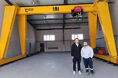

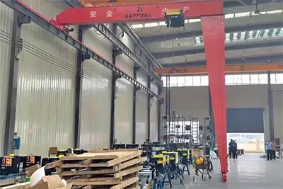
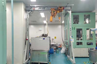 Aluminum gantry crane with low headroom chain hoist with capacity up to 10 ton for light loads and light duty material handling
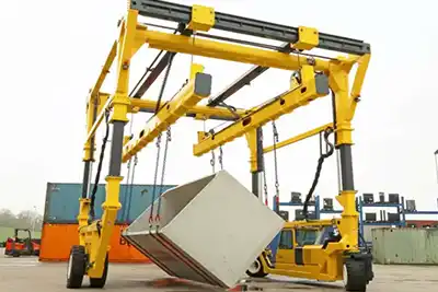
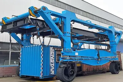
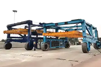 straddle carrier with low headroom design for confined space
 Customized TBM Gantry Crane Engineering Solutions for Non-Standard Tunnel Conditions
- Growing complexity of metro, railway, hydropower, and utility tunnel projects
- Increasing use of deep shafts and confined underground construction environments
- Why standard overhead and gantry crane configurations often fail in TBM applications
- Importance of project-specific crane engineering for safety, productivity, and lifecycle cost reduction
- TBM segment lifting and installation
- Muck bucket and spoil handling
- Vertical shaft material transportation
- TBM cutterhead maintenance
- Pipe and reinforcement cage handling
- Underground equipment installation
- Common lifting capacities from 10 ton to 100 ton+
- Typical customized spans from 18m to 36m
- High lifting heights up to 50m+
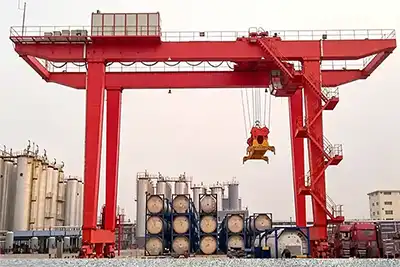
- Single girder and double girder tunnel gantry crane configurations
Customized TBM Gantry Crane Systems
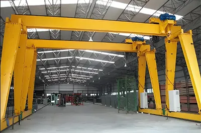
Customized TBM gantry cranes are specially engineered lifting systems designed for tunnel boring machine (TBM) construction projects. Unlike standard industrial gantry cranes, these cranes are built around the actual tunnel environment, shaft dimensions, underground working space, and material handling process.
In tunnel construction, the crane is often one of the most important pieces of equipment on site. It supports segment handling, shaft lifting, equipment installation, spoil transportation, and TBM maintenance operations. If the crane design does not match the project conditions, tunnel construction efficiency can drop quickly.
That is why many contractors now use customized tunnel gantry crane systems instead of standard overhead lifting equipment.
A customized TBM gantry crane is a rail-mounted lifting system designed specifically for underground tunnel construction and shaft operations.
The crane usually travels on rails installed near tunnel shafts, portal areas, or material handling zones. It lifts heavy loads vertically and horizontally during TBM excavation and tunnel lining operations.
Typical lifting tasks include:
- Tunnel segment transportation
- Muck bucket lifting
- Pipe handling
- TBM component maintenance
- Underground equipment installation
- Reinforcement cage lowering
Unlike general industrial cranes, tunnel gantry cranes are designed around:
- Tunnel dimensions
- Shaft depth
- Underground clearance
- Continuous lifting cycles
- Harsh environmental conditions
In many projects, the crane operates almost continuously during excavation progress.
A TBM gantry crane works by combining several coordinated motions to move loads safely inside tunnel construction areas.
The crane typically performs:
- Hoisting movement for lifting and lowering loads
- Trolley travel for horizontal movement across the span
- Gantry travel along runway rails
- Precise positioning during installation work
The load is lifted using a hoist mounted on the trolley system. The trolley moves across the main girder while the entire crane travels along rail tracks installed on the ground.
In tunnel construction projects, crane movement must remain smooth and stable because many loads are:
- Heavy
- Irregularly shaped
- Suspended over deep shafts
- Installed inside confined underground areas
For this reason, tunnel gantry cranes often use:
- Variable frequency drive (VFD) control
- Anti-sway systems
- Dual-speed hoisting
- Synchronized lifting control
- Real-time load monitoring
These systems improve positioning accuracy and reduce lifting risks during underground operations.
Difference Between Standard Gantry Cranes and Tunnel-Specific Designs
At first glance, a tunnel gantry crane may look similar to a standard industrial gantry crane. However, the engineering requirements are very different.
Standard gantry cranes are usually designed for:
- Factories
- Warehouses
- Outdoor storage yards
- Open construction sites
Tunnel construction environments create additional challenges that require customized engineering.
Common problems include:
- Insufficient lifting height
- Poor hook coverage
- Oversized crane structure
- Limited underground installation access
- Weak protection against dust and moisture
- Poor deep shaft lifting stability
A standard crane may technically lift the load weight, but still fail operationally because it does not fit the tunnel workflow.
Customized TBM gantry cranes are designed to solve these underground lifting challenges.
Common tunnel-specific features include:
- Customized spans from 18m to 36m
- High lifting heights up to 50m+
- Low headroom crane structures
- Heavy-duty double girder configurations
- Compact gantry leg design
- Rail-mounted travel systems
- Deep shaft hoisting systems
- Anti-corrosion protection
- Dust-proof electrical systems
In practical tunnel construction work, these modifications improve both lifting safety and operational efficiency.
Most TBM gantry cranes use rail-mounted traveling systems.
The crane moves on rails installed along the shaft or construction area. Rail-mounted systems provide better stability and positioning accuracy compared with rubber-tired crane systems.
This becomes especially important during:
- Deep shaft lifting
- Tunnel segment positioning
- Heavy TBM component handling
- High-frequency lifting operations
Rail-mounted gantry crane systems are commonly used in:
- Metro tunnel projects
- Railway tunnel construction
- Hydropower tunnels
- Utility tunnel projects
Advantages of rail-mounted tunnel gantry cranes include:
- Stable crane travel
- Better heavy-load handling
- Improved positioning accuracy
- Lower operational sway
- Better long-term durability
In some projects, the runway system is also customized to fit temporary tunnel construction layouts and restricted underground space.
Typical Tunnel Construction Environments Requiring Customized Crane Solutions
Tunnel construction environments are very different from normal industrial lifting sites. Space is restricted, underground conditions are harsh, and lifting operations are often continuous.
Because of this, customized crane engineering becomes necessary.
Tunnel portals often provide very limited working space.
The crane may need to operate around:
- Trucks
- Conveyor systems
- TBM backup equipment
- Temporary structures
- Material storage areas
To improve space utilization, tunnel cranes may use:
- Compact gantry leg designs
- Narrow-span layouts
- Low headroom structures
- Customized hook approach dimensions
Deep shafts create major lifting challenges.
As lifting height increases, problems such as hook sway and rope instability become more serious.
Typical deep shaft crane requirements include:
- 30m to 50m+ lifting heights
- Heavy-duty hoisting systems
- Dual brake systems
- Anti-sway technology
- Reinforced structural design
Deep shaft tunnel cranes are commonly used in metro and hydropower projects.
Some underground construction zones have very limited vertical clearance.
In these situations, standard crane designs may not fit safely inside the working area.
Low headroom gantry cranes help maximize:
- Hook lifting height
- Underground clearance
- Equipment movement space
Compact trolley arrangements are often used in these environments.
Tunnel construction often produces:
- Slurry
- Mud
- Abrasive dust
- Water spray
These materials can damage crane components quickly if the crane is not properly protected.
Tunnel cranes operating in these conditions commonly use:
- Sealed motors
- Enclosed cable systems
- Corrosion-resistant coatings
- Heavy-duty protective covers
Underground tunnels often have:
- High humidity
- Water leakage
- Corrosive groundwater
- Condensation buildup
These conditions affect electrical reliability and structural durability.
To improve long-term performance, tunnel gantry cranes may include:
- Anti-condensation heaters
- Moisture-resistant electrical systems
- Galvanized components
- Epoxy protective coatings
- Stainless steel accessories
Proper environmental protection is especially important in hydropower tunnels and long-duration underground construction projects.
Why Standard Gantry Cranes Are Not Suitable for Many TBM Projects
At first glance, a standard gantry crane may appear capable of handling tunnel construction work. The lifting capacity may look sufficient on paper, and the crane may even be commonly used in factories or outdoor construction sites. However, TBM tunnel projects create very different operating conditions.
Underground tunnel construction involves restricted space, deep shaft lifting, continuous heavy-duty operation, and complicated material handling paths. In these environments, standard gantry crane designs often create operational limitations, installation difficulties, and long-term maintenance problems.
That is why many contractors choose customized TBM gantry cranes designed specifically for underground construction conditions.
Space Limitations in Underground Tunnel Construction
Space is one of the biggest challenges in tunnel projects.
Unlike open industrial workshops or outdoor storage yards, TBM construction sites usually have very limited operating space. Every area inside the shaft or tunnel portal may already be occupied by equipment, material transport systems, ventilation ducts, or temporary support structures.
A crane that works well above ground may become difficult to operate underground.
Tunnel shafts and portal zones often provide very little room for crane assembly and operation.
In many metro and railway tunnel projects, the crane must be installed between:
- Shaft retaining walls
- TBM launch structures
- Temporary construction platforms
- Material storage zones
- Vehicle access lanes
Sometimes the crane structure itself becomes too large for the available site area.
This creates problems such as:
- Difficult crane erection
- Limited maintenance access
- Reduced operational clearance
- Unsafe equipment movement paths
Because of this, tunnel projects often require:
- Compact gantry crane structures
- Modular assembly design
- Narrow leg configurations
- Customized crane dimensions
Modular tunnel gantry cranes are especially useful because they can be assembled in sections inside confined construction sites.
Hook approach distance becomes very important in tunnel construction.
In standard gantry cranes, the hook may not travel close enough to the shaft edge or tunnel wall. This reduces the effective lifting area and creates blind lifting zones.
For tunnel segment handling and shaft lifting operations, even small hook positioning limitations can affect construction efficiency.
Common problems include:
- Inability to reach segment storage positions
- Reduced lifting coverage inside shafts
- Difficult equipment positioning
- Increased manual load adjustment
Customized tunnel gantry cranes often use:
- Optimized trolley arrangements
- Reduced hook offset design
- Low headroom structures
- Compact girder layouts
These modifications help maximize usable lifting space in restricted underground environments.
Modern TBM projects involve many systems operating simultaneously.
The gantry crane may need to work around:
- TBM backup cars
- Conveyor belts
- Ventilation systems
- Slurry pipelines
- Electrical cable routes
- Underground transport vehicles
A standard gantry crane is usually not designed for these complicated layouts.
If crane dimensions are not properly coordinated with the site arrangement, operational conflicts can occur.
Typical issues include:
- Crane legs blocking transport routes
- Trolley interference with ventilation systems
- Insufficient clearance above conveyors
- Restricted maintenance access around the crane
This is why customized tunnel gantry crane engineering often includes detailed layout planning before production begins.
Non-Standard Shaft and Tunnel Geometry
Tunnel construction sites rarely follow perfect standard dimensions.
Shaft layouts, runway alignment, and underground foundation conditions often vary from project to project. Standard gantry crane dimensions may not match the actual construction geometry.
Customized crane engineering becomes necessary to ensure safe operation and proper load distribution.
Some tunnel shafts are narrow and deep, while others may be wide with offset lifting zones.
The crane span and lifting arrangement must match the actual shaft dimensions.
If the crane span is not properly selected, problems may include:
- Poor load coverage
- Limited lifting area
- Unbalanced structural loading
- Restricted underground access
Typical customized tunnel gantry crane spans include:
- 18m span
- 22m span
- 26m span
- 30m span
- 36m span
The final span depends on:
- Shaft width
- Vehicle access requirements
- Segment storage arrangement
- Conveyor positioning
Tunnel projects do not always allow perfectly straight runway installation.
Runway systems may need to avoid:
- Existing structures
- Excavation equipment
- Temporary foundations
- Utility lines
This creates non-standard runway layouts where standard crane travel systems may not operate smoothly.
Customized rail-mounted gantry cranes can be designed to handle:
- Offset rail positioning
- Irregular travel paths
- Limited rail spacing
- Uneven runway alignment
Proper runway engineering is critical for maintaining crane travel stability during heavy lifting operations.
Tunnel construction sites often involve temporary civil works and uneven ground conditions.
Unlike permanent industrial workshops, underground crane foundations may experience:
- Settlement
- Vibration
- Mud contamination
- Water accumulation
- Temporary structural movement
These conditions can affect:
- Crane wheel loading
- Rail alignment
- Structural stability
- Travel smoothness
Tunnel gantry cranes usually require reinforced wheel assemblies, adjustable support systems, and customized rail foundation design to maintain stable operation.
Heavy and Specialized Tunnel Loads
Tunnel projects involve many types of heavy and irregular loads that standard gantry cranes are not designed to handle efficiently.
The challenge is not only load weight, but also load shape, lifting frequency, positioning accuracy, and underground operating conditions.
Tunnel lining segments are among the most common loads handled in TBM construction.
These precast concrete segments are:
- Heavy
- Large in diameter
- Irregular in shape
- Sensitive to impact damage
Segment handling usually requires:
- Stable hoisting
- Smooth acceleration and braking
- Accurate positioning
- Anti-sway control
Standard industrial cranes may not provide the positioning precision required for continuous tunnel segment installation.
Customized tunnel segment gantry cranes often use:
- Synchronized hoists
- VFD speed control
- Segment lifting beams
- Dual trolley systems
TBM maintenance involves lifting oversized and high-value components.
These may include:
- Cutterhead sections
- Bearings
- Drive systems
- Shield components
- Hydraulic equipment
Many of these loads are irregularly shaped and unevenly balanced.
This requires:
- Customized lifting frames
- Heavy-duty spreader beams
- Precise low-speed control
- High structural stability
A standard gantry crane may lack the lifting precision and heavy-duty design needed for these operations.
Reinforcement cages used in shaft construction are often long and difficult to control during lifting.
Problems during lifting may include:
- Swinging
- Bending
- Rotation
- Interference with shaft walls
To improve safety and positioning accuracy, tunnel cranes may use:
- Multi-point lifting systems
- Adjustable spreader beams
- Guided lowering systems
- Slow-speed positioning control
Tunnel projects frequently involve oversized equipment installation underground.
Examples include:
- Conveyor systems
- Pump stations
- Ventilation fans
- Rail systems
- Steel support frames
These loads may exceed the practical handling limits of standard industrial cranes because of restricted underground operating space.
Customized tunnel gantry cranes improve lifting flexibility and positioning control during equipment installation.
Continuous Heavy-Duty Tunnel Operations
Tunnel construction is not occasional lifting work. In many TBM projects, the crane operates continuously for long periods every day.
This creates much higher operational demands compared with standard industrial lifting applications.
TBM excavation often runs continuously.
The gantry crane may perform:
- Segment lifting every few minutes
- Continuous muck bucket handling
- Repeated material transfer cycles
- Frequent equipment repositioning
High-frequency operation increases wear on:
- Motors
- Brakes
- Wire ropes
- Wheel assemblies
- Structural connections
Tunnel gantry cranes must therefore be designed for continuous-duty operation instead of occasional lifting service.
Many tunnel gantry cranes operate under heavy-duty or severe-duty classifications.
This affects:
- Structural design
- Motor selection
- Brake capacity
- Gearbox durability
- Hoisting system configuration
Double girder gantry cranes are commonly used because they provide:
- Better load distribution
- Higher fatigue resistance
- Improved structural rigidity
- Greater operational stability
Continuous lifting cycles create long-term fatigue stress on the crane structure.
In tunnel projects, fatigue loading may become more serious because of:
- Heavy repetitive lifting
- Dynamic loading during deep shaft operation
- Uneven load movement
- Continuous trolley travel
Over time, this can affect:
- Girder welds
- Structural joints
- Rail alignment
- Wheel assemblies
Customized TBM gantry cranes are often reinforced using:
- Heavy-duty box girders
- Structural stiffeners
- Finite element analysis (FEA)
- Fatigue-resistant steel structures
These improvements help extend crane service life under demanding tunnel construction conditions.
Customized Span Engineering for TBM Gantry Cranes
Span design is one of the most important engineering factors in a TBM gantry crane project. In tunnel construction, the crane span directly affects lifting coverage, shaft accessibility, transportation clearance, structural stability, and overall construction efficiency.
A gantry crane with the wrong span may still lift the required load, but daily operation can become difficult and inefficient. In some projects, poor span selection creates traffic conflicts, restricted lifting zones, or unstable load distribution across the crane structure.
That is why customized span engineering is widely used in modern tunnel gantry crane systems.
Unlike standard industrial gantry cranes, tunnel cranes are usually designed around the actual shaft dimensions and underground construction layout.
In TBM tunnel construction, the crane span controls how effectively materials can move through the shaft and construction area.
The span affects:
- Hook coverage
- Underground traffic flow
- Equipment positioning
- Crane stability
- Structural loading
- Installation space utilization
A wider span increases working coverage but also increases structural loading and crane cost. A smaller span reduces structural weight, but may limit underground access and lifting flexibility.
The goal is to find a practical balance between coverage, stability, and construction efficiency.
The tunnel shaft width is usually the first factor considered during span selection.
The crane span must allow enough clearance for:
- Segment storage areas
- Material handling lanes
- Truck movement
- Conveyor systems
- Maintenance access
- Underground equipment transfer
If the span is too narrow:
- The hook may not reach all lifting positions
- Material movement becomes restricted
- Equipment congestion increases
If the span is unnecessarily large:
- Structural deflection increases
- Wheel loading becomes heavier
- Crane cost rises significantly
In practical tunnel construction projects, the crane span is normally selected slightly wider than the main operational area to improve lifting flexibility.
For example:
- Compact shafts may use 18m spans
- Medium metro shafts often use 22m–26m spans
- Large TBM launch shafts may require 30m–36m spans
Tunnel construction sites require continuous movement of materials and equipment below the crane.
The gantry crane span must provide enough space for:
- Tunnel segment transportation
- Muck bucket movement
- Underground trucks
- Pipe transfer
- Reinforcement cage handling
In many TBM projects, multiple transportation systems operate simultaneously.
For example:
- Trucks may transport materials on one side
- Conveyor belts may run through the center
- Segment storage areas may occupy the opposite side
The crane span must allow these systems to operate safely without interference.
Poor span planning can create:
- Traffic bottlenecks
- Unsafe lifting paths
- Limited equipment access
- Reduced operational efficiency
This is one reason why customized tunnel gantry crane engineering is often coordinated together with overall shaft layout planning.
Modern tunnel projects often use conveyors for continuous spoil removal.
At the same time, vehicles may transport:
- Tunnel segments
- Pipes
- Reinforcement cages
- Mechanical equipment
The crane structure must integrate smoothly with these transportation systems.
Important design considerations include:
- Conveyor height clearance
- Truck travel paths
- Crane leg positioning
- Maintenance access routes
- Safe operator visibility
In some projects, gantry crane legs are specially offset or narrowed to improve underground traffic movement.
Low-clearance tunnel portals may also require compact structural designs to avoid interference with ventilation systems and TBM backup equipment.
Typical Customized Span Ranges in TBM Gantry Cranes
In TBM tunnel construction, crane span is not a fixed parameter. It is adjusted according to shaft geometry, material flow layout, underground traffic space, and construction method. A correct span selection directly affects lifting efficiency, equipment clearance, and safe movement inside the tunnel working zone.
Different tunnel projects use different span configurations. The most commonly applied ranges are 18m, 22–26m, and 30–36m spans, each serving different construction scales and operational needs.
18m Span Gantry Cranes
18m span gantry cranes are widely used in compact tunnel construction environments where working space is limited and the shaft opening is relatively small.
These cranes are commonly selected for:
- Small tunnel shafts
- Utility tunnel projects
- Compact metro access shafts
- Maintenance lifting operations
In these applications, the main requirement is not wide coverage, but stable and safe lifting within a confined area.
Because the span is relatively short, the crane structure is generally more compact. This makes it easier to install and operate in restricted underground conditions.
An 18m span design offers several practical benefits in tunnel construction projects:
- Lower structural weight, reducing foundation load requirements
- Easier installation and faster assembly on site
- Reduced wheel load pressure on rails
- Better adaptability to narrow tunnel portals
- Lower manufacturing and transportation cost
In many utility tunnel and small metro projects, these advantages make 18m span cranes a practical choice when lifting demand is moderate.
However, a smaller span also means reduced lifting coverage.
This can lead to:
- Limited working radius inside the shaft
- Reduced flexibility for segment placement
- More frequent crane repositioning
- Restricted material storage layout
Because of this, hook approach design becomes more important. Even with a smaller span, the crane must still reach all required lifting points inside the working zone without interference.
Tunnel portal areas are often the most space-restricted parts of the entire construction site.
In many projects, available space must accommodate:
- Retaining walls and support structures
- Temporary construction facilities
- Material storage areas
- Vehicle access lanes
- TBM launch equipment
In such conditions, a compact span crane like 18m becomes a practical solution.
It can fit more easily within the limited portal width while still maintaining stable lifting performance.
This makes it suitable for urban metro construction sites where surrounding infrastructure limits available space.
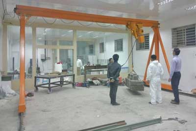
Small shafts are commonly used in:
- Utility tunnel projects
- Pipe network installations
- Cable tunnel systems
- Maintenance access shafts
These projects usually do not require wide-span heavy lifting cranes.
Instead, the main lifting tasks include:
- Pipe installation
- Reinforcement cage lowering
- Material transfer between surface and underground
- Routine maintenance lifting work
In these cases, single girder gantry cranes or light-duty double girder cranes are often sufficient.
The focus is on practicality, installation speed, and cost control rather than maximum lifting coverage.
When selecting an 18m span gantry crane for tunnel projects, engineers usually consider:
- Shaft width and clearance conditions
- Type and size of materials being lifted
- Frequency of lifting operations
- Available installation space at tunnel entrance
- Future expansion or relocation requirements
In real TBM projects, the final decision is rarely based on span alone. It is always matched with lifting height, load weight, and underground construction workflow.
A properly selected 18m span crane can provide stable performance in compact tunnel environments without unnecessary structural complexity.
22m–26m Span Gantry Crane Configurations
The 22m to 26m span range is one of the most widely used configurations in medium-scale TBM tunnel projects. It is often selected when the project requires a balance between lifting flexibility, structural performance, and overall investment cost.
This span range is commonly used in:
- Medium metro tunnel projects
- Railway tunnel construction
- TBM launch and retrieval shafts
- Underground station construction zones
In these environments, the crane must support continuous lifting operations while still fitting within a controlled construction layout.
22m–26m span tunnel gantry cranes are typically used for:
- Tunnel segment lifting and installation
- Shaft material handling operations
- Muck bucket transfer during TBM excavation
- TBM maintenance and support lifting tasks
These tasks require stable lifting behavior and consistent operational accuracy, especially during repetitive underground construction cycles.
In this span range, double girder gantry cranes are commonly used. The reason is simple: tunnel operations involve heavy and frequent loads, and structural rigidity becomes more important than minimal cost.
Typical configurations include:
- 32 ton gantry crane systems
- 50 ton heavy-duty gantry cranes
- Rail-mounted traveling systems
- VFD-controlled hoisting and trolley movement
- Anti-sway lifting systems for segment installation
These configurations help maintain stable lifting performance in medium-depth tunnel environments.
Metro and railway tunnel shafts usually require enough working space to support multiple construction activities at the same time.
A typical shaft layout may include:
- Segment storage zones
- Vehicle access lanes
- Conveyor belt systems
- TBM backup equipment areas
- Temporary material staging zones
Because of this, the crane span must support more than just lifting. It must also allow safe movement of materials and equipment inside the same working area.
The 22m–26m span range often provides enough flexibility to manage these combined requirements without making the crane structure too heavy or difficult to control.
In practical tunnel construction, this span range is often chosen because it provides a stable middle point between compact and large-scale crane systems.
It helps achieve:
- Sufficient lifting coverage across the shaft
- Stable structural performance under heavy loads
- Manageable wheel load distribution on rails
- Reasonable installation and transportation effort
At the same time, it avoids the higher structural cost and engineering complexity of very large span systems.
One of the main reasons the 22m–26m span range is widely used is its balance between performance and investment.
Compared with larger 30m–36m span cranes, this range offers:
- Lower structural weight, making fabrication easier
- Better control of girder deflection under load
- Reduced wheel pressure on runway rails
- Simpler installation and alignment process
These advantages make it suitable for projects that require reliable daily operation without extreme structural demands.
In most medium TBM tunnel projects, this balance is often considered more practical than maximizing crane span.
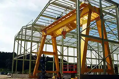
30m–36m Heavy-Duty Tunnel Gantry Cranes
When tunnel projects become larger and more complex, wider span gantry cranes are required. The 30m–36m span range is typically used in large-scale infrastructure projects where shaft dimensions, load sizes, and operational requirements exceed medium project limits.
These cranes are usually heavy-duty double girder systems designed for continuous and demanding operation.
30m–36m span gantry cranes are commonly used in:
- Large TBM launch and retrieval shafts
- Hydropower tunnel construction projects
- Major railway tunnel infrastructure works
- Large metro interchange stations
These projects often involve oversized TBM components, wide excavation areas, and multiple material handling zones operating simultaneously.
The wider span allows cranes to cover a larger working area without frequent repositioning.
Large infrastructure tunnel construction often includes:
- Oversized TBM equipment handling
- Wide shaft openings for multi-directional lifting
- Multiple transport lanes for materials and vehicles
- Continuous high-frequency lifting cycles
Because of these conditions, crane design must support both heavy loads and long operating hours without performance loss.
Wide shaft environments introduce additional engineering requirements that do not appear in smaller tunnel projects.
Typical lifting operations include:
- Tunnel segment transfer across wide working areas
- Muck bucket lifting from deep excavation zones
- Heavy equipment installation and positioning
- Reinforcement cage handling for large structural sections
As span increases, structural forces acting on the crane also increase significantly.
Without proper design optimization, wide-span tunnel gantry cranes may face:
- Increased girder deflection under heavy loads
- Uneven wheel loading across rail systems
- Higher fatigue stress on structural joints
- Reduced trolley stability during movement
These issues can affect both safety and long-term reliability if not properly addressed during design.
To manage these challenges, 30m–36m span gantry cranes often include:
- Reinforced box girder structures
- Advanced finite element structural analysis (FEA)
- Optimized load distribution design
- High-strength steel construction
- Enhanced rail alignment and wheel system design
These engineering measures help maintain stable operation even under heavy-duty, continuous tunnel construction conditions.
Structural Engineering Considerations in TBM Gantry Crane Design
Span selection in TBM gantry cranes is not only about how wide the crane can cover a tunnel shaft. It directly affects structural behavior, long-term durability, and operational safety under real tunnel construction conditions.
As span increases, the crane structure is subjected to higher bending moments, more complex load paths, and stronger dynamic forces during lifting and travel operations. Because of this, structural engineering becomes a key part of tunnel crane design rather than a secondary consideration.
Deflection Control
Deflection refers to the elastic bending of the crane girder when it is subjected to load. In tunnel gantry cranes, this becomes more noticeable as span length increases and lifting loads become heavier.
Large-span cranes naturally experience higher deflection, especially during:
- Full-load lifting operations
- Long-distance trolley movement
- Segment installation work
- Deep shaft lowering and lifting cycles
Even small deflection at the girder level can affect the precision of load positioning at the hook level, particularly in deep tunnel shafts.
If deflection is not properly controlled, it can lead to several operational issues:
- Reduced smoothness of trolley travel along the girder
- Lower accuracy in hook positioning during segment installation
- Increased fatigue stress on structural joints and welds
- Higher risk of uneven load distribution during lifting
- Reduced operator confidence in precision lifting tasks
In TBM tunnel construction, where segment alignment is critical, even minor inaccuracies can slow down installation progress.
To manage deflection in medium and large span tunnel gantry cranes, several structural design methods are commonly used:
- Reinforced box girder construction to increase bending resistance
- Internal structural stiffeners to improve rigidity
- Optimized girder depth based on span-to-load ratio
- Finite Element Analysis (FEA) during design validation
These measures help ensure that the crane maintains acceptable deflection limits even under repeated heavy-duty lifting cycles.
Stability Optimization
Stability in tunnel gantry cranes refers to the ability of the crane structure to remain balanced and controlled during lifting, travel, and load positioning operations.
In tunnel environments, cranes must operate under continuous working cycles, often in confined and complex layouts.
As span increases, the crane becomes more sensitive to:
- Torsional deformation during lifting
- Dynamic vibration during trolley movement
- Uneven wheel loading across rail systems
- Load imbalance during segment handling
- Sudden acceleration or braking forces
These effects are more pronounced in deep shaft or high-frequency TBM operations.
To maintain stable operation, tunnel gantry cranes often incorporate:
- Double girder structural systems for higher rigidity
- Reinforced gantry legs to reduce lateral movement
- Balanced wheel load design across both rails
- Optimized rail spacing for improved structural equilibrium
In practice, these design elements work together to reduce unwanted movement and improve control during heavy lifting cycles.
Load Distribution
Proper load distribution is essential for both crane structural integrity and rail system durability.
In TBM tunnel projects, cranes frequently handle heavy and repetitive loads such as tunnel segments, muck buckets, and TBM components.
If load distribution is not properly engineered, long-term operational problems may occur.
Uneven or poorly controlled load distribution can result in:
- Irregular wheel wear on crane traveling systems
- Localized rail deformation or damage
- High stress concentration in girder connections
- Reduced service life of crane runway structures
- Potential instability during heavy lifting operations
These issues not only increase maintenance costs but can also affect construction safety and schedule efficiency.
Customized TBM gantry cranes are designed to distribute loads more evenly across the entire structure.
This is achieved through:
- Structural balancing of girder and leg geometry
- Optimized wheel spacing and axle design
- Reinforced runway beam coordination
- Load path analysis during engineering design
By managing how forces travel through the crane structure, long-term durability and operational reliability are significantly improved.
Wind Resistance for Outdoor Portal Sections
In many tunnel construction projects, gantry cranes operate near tunnel entrances or portal zones where part of the crane is exposed to outdoor environmental conditions.
Unlike fully enclosed underground areas, these portal sections are subject to wind loads that can influence crane stability.
Strong wind conditions can affect crane operation in several ways:
- Reduced stability during crane travel along rails
- Increased swing of suspended loads
- Additional stress on structural components
- Possible rail movement or micro-sliding in extreme conditions
These effects become more significant when lifting large tunnel segments or operating at higher hook elevations.
To ensure safe operation in outdoor tunnel portal environments, cranes are often equipped with specialized wind protection systems such as:
- Rail clamp systems to prevent unintended crane movement
- Wind speed alarm devices for operator warning
- Storm locking mechanisms for parked crane stability
- Reinforced structural design for lateral wind resistance
These systems help ensure that crane operation remains stable and controlled even under variable weather conditions at tunnel entrances.
Summary
Structural engineering in TBM gantry crane design is directly linked to span selection and real-world tunnel operating conditions.
Key considerations include:
- Controlling deflection to maintain lifting precision
- Optimizing stability under dynamic and continuous operation
- Ensuring even load distribution across structure and runway
- Enhancing wind resistance for outdoor portal environments
Together, these factors determine whether a tunnel gantry crane can operate reliably under the demanding conditions of modern TBM construction projects.
High Lifting Height Design for Deep Shaft Operations
Deep shaft TBM construction pushes gantry crane systems into operating conditions that are very different from normal industrial lifting. When lifting heights reach 30m, 40m, and especially 50m or more, the crane must manage not only heavier loads but also longer suspension distances, slower response behavior, and higher dynamic instability.
In these environments, high lifting height design becomes a core engineering requirement rather than an optional feature. The crane must ensure safe vertical transport between surface level and underground working zones, often in continuous operation cycles.
Why Deep Shaft Lifting Requires Specialized Engineering
Deep shaft lifting introduces a combination of mechanical, structural, and control challenges that standard gantry cranes are not originally designed to handle.
Unlike short-distance lifting in factories or open yards, tunnel shafts require long vertical travel inside confined spaces with limited visibility and complex underground conditions.
In deep shaft construction, materials and equipment must be transported vertically over long distances, often exceeding 50 meters.
- Lowering precast tunnel segments into underground assembly zones
- Raising muck buckets filled with excavated soil or rock
- Transporting TBM components during installation or maintenance
- Moving reinforcement cages and steel structures
- Installing underground mechanical and electrical equipment
As lifting height increases, several technical issues become more pronounced:
- Wire rope elongation under load
- Increased sensitivity to load imbalance
- Reduced precision at landing position
- Higher impact forces during braking and stopping
Even small positioning errors at the top of a long lift can result in significant misalignment at the bottom of the shaft.
Deep shaft operations naturally involve longer lifting and lowering cycles compared to shallow or surface-level operations.
- Load engagement at surface level
- Vertical lifting over 30–50 meters or more
- Stabilization during upward travel
- Controlled lowering into underground working zones
- Final precise positioning for installation
Because of this extended cycle, crane control systems must ensure smooth acceleration and deceleration to avoid sudden load movement.
If motion control is not properly optimized, it can lead to:
- Load oscillation during travel
- Segment positioning delays
- Increased operator correction work
- Reduced installation efficiency
This is why deep shaft cranes rely heavily on variable speed and precision control systems.
One of the most significant challenges in high lifting height operations is load sway.
As the lifting height increases, the suspended load behaves more like a pendulum. The longer the wire rope, the more difficult it becomes to control lateral movement.
Sway can be triggered by:
- Rapid acceleration or deceleration
- Wind influence near shaft openings
- Uneven load distribution
- Sudden braking actions
- Operator control adjustments during lifting
In tunnel environments, load sway can directly impact safety and installation accuracy.
Common consequences include:
- Difficulty aligning tunnel segments
- Risk of collision with shaft walls
- Slower installation cycles
- Increased safety exposure for workers below
To manage this, modern TBM gantry cranes integrate anti-sway control systems with precise motion regulation.
Typical High-Lift Applications
High lifting height gantry cranes are essential in deep shaft and underground tunnel construction projects where vertical transport is continuous and mission-critical.
Deep shafts serve as primary access points for TBM installation and material transport.
Typical operations include:
- Excavated material removal from underground zones
- Lowering of tunnel lining segments
- Installation of TBM components
- Structural steel and support system handling
In many metro and hydropower projects, shaft depths frequently exceed 30m to 50m+, requiring high-stability crane systems designed for long vertical travel.
Precast concrete tunnel segments are transported from the surface and lowered into underground assembly zones.
This process requires:
- Smooth and controlled lowering speed
- High positional accuracy at landing point
- Stable load behavior during descent
Even slight misalignment can lead to:
- Segment edge damage
- Installation delays
- Additional manual adjustment work
Therefore, segment lowering is considered one of the most precision-sensitive lifting tasks in TBM construction.
Spoil removal is a continuous operation during TBM excavation.
Buckets filled with excavated soil or rock are lifted repeatedly from underground to the surface.
Key operational characteristics include:
- High-frequency lifting cycles
- Continuous operation during excavation phases
- Time-sensitive material removal process
Critical requirements include:
- Fast but controlled lifting speed
- Reliable braking system performance
- Durable wire rope and drum systems
- High operational stability under repetitive load cycles
Large-scale underground equipment installation requires careful and precise lifting control.
Typical equipment includes:
- Ventilation systems
- Pump stations
- Conveyor components
- Electrical control cabinets
These installations often occur in confined spaces where positioning accuracy is more important than speed.
Key requirements include:
- Low-speed precision control
- Stable load suspension
- Fine positioning capability
- Safe braking and holding systems
Key High-Lift Engineering Features
To ensure safe and stable operation under deep shaft conditions, TBM gantry cranes incorporate several specialized engineering systems.
High lifting height requires long wire rope lengths, which increases demands on drum capacity and winding stability.
Key design features include:
- Large-diameter drum construction
- Multi-layer rope winding design
- Precision-machined rope grooves
- High wear-resistant drum surfaces
These features help maintain smooth rope alignment and reduce wear during long lifting cycles.
Dual braking systems are essential safety components in deep shaft cranes.
They provide:
- Primary working brake for normal operation
- Secondary emergency brake for safety backup
This redundancy ensures safe load control even in the event of:
- Power failure
- Electrical fault
- Mechanical brake malfunction
Dual braking is especially critical when handling heavy tunnel segments or TBM components.
Anti-sway systems are designed to reduce oscillation during lifting and lowering operations.
They help:
- Stabilize suspended loads
- Improve positioning accuracy
- Reduce operator correction time
- Enhance lifting safety during long vertical travel
This technology becomes more important as lifting height increases.
Encoder systems provide real-time feedback on hook position.
They enable:
- Accurate vertical position tracking
- Controlled lowering into underground zones
- Prevention of over-lifting or over-lowering
- Integration with automated control systems
This is especially important during precise segment installation tasks.
VFD control systems regulate motor speed during lifting, lowering, and travel operations.
Benefits include:
- Smooth acceleration and deceleration
- Reduced mechanical shock loads
- Improved load stability during motion
- Better energy efficiency
In deep shaft applications, smooth motion control is essential for maintaining load safety.
Safety Requirements for 50m+ Lifting Heights
When lifting heights exceed 50 meters, additional safety systems are required to ensure stable and reliable operation under high-risk conditions.
Emergency braking systems are designed to immediately stop crane movement in critical situations.
They help:
- Prevent uncontrolled load descent
- Stop trolley or hoist movement instantly
- Protect personnel working in underground zones
This system is a key safety requirement in deep shaft TBM operations.
Overload protection prevents the crane from operating beyond its rated capacity.
It helps:
- Protect structural components
- Prevent hoist damage
- Reduce risk of wire rope failure
- Maintain safe operating conditions
Load variations are common in tunnel construction, making this system essential.
Real-time monitoring systems provide continuous operational data during lifting.
They typically track:
- Load weight
- Hook position
- Motor temperature
- System fault status
This allows operators to respond quickly to abnormal conditions.
Redundancy ensures that critical systems remain functional even if one component fails.
Common redundant systems include:
- Backup braking units
- Secondary limit switches
- Dual control circuits
- Emergency power systems
In deep shaft environments, redundancy significantly improves operational safety due to limited accessibility for manual intervention.
Summary
High lifting height design in TBM gantry cranes is a combination of mechanical strength, control precision, and safety redundancy.
As lifting height increases toward and beyond 50 meters, engineering focus shifts toward:
- Controlling load sway during long vertical travel
- Ensuring smooth and precise lifting cycles
- Maintaining structural stability under dynamic load conditions
- Providing multiple layers of operational safety
These factors are essential for safe and efficient deep shaft tunnel construction in modern TBM projects.
Structural Customization for Confined Tunnel Conditions
Tunnel construction environments rarely provide ideal space conditions. In TBM projects, cranes must operate inside narrow shafts, low-clearance portals, and congested underground working zones. Standard gantry crane structures often become too large, too rigid in layout, or too difficult to install.
For this reason, structural customization becomes a core requirement. Tunnel gantry cranes are designed not only for lifting capacity, but also for adaptability to confined geometry, restricted access, and phased construction conditions.
Low Headroom Tunnel Gantry Crane Designs
Low headroom gantry cranes are specifically developed for tunnel environments where vertical space is limited. These conditions are common at tunnel portals, shaft entrances, and underground working chambers where multiple systems are installed in a tight layout.
The main objective of low headroom design is simple: maximize usable hook height while minimizing structural height.
In confined tunnel areas, reducing overall crane height is often necessary to ensure safe clearance under roof structures, ventilation systems, and TBM backup equipment.
Typical design adjustments include:
- Lower main girder profile
- Compact hoist arrangement integrated within girder space
- Reduced end carriage height
- Optimized structural geometry for vertical clearance
This allows the crane to operate in spaces where standard gantry cranes would not physically fit.
Trolley systems in low headroom cranes are redesigned to reduce vertical space consumption while maintaining lifting capacity.
Common features include:
- Low-profile trolley frame design
- Integrated hoist and trolley structure
- Side-mounted or recessed motor arrangement
- Optimized wheel and rail contact geometry
These adjustments help ensure smooth movement without sacrificing hook height, which is critical during tunnel segment installation and shaft lifting operations.
Even with reduced structural height, tunnel cranes must maintain sufficient hook travel for deep shaft operations.
To achieve this, engineering solutions often include:
- Shortened structural dead zones above the hook
- Optimized hoisting drum placement
- High-efficiency wire rope routing systems
- Compact pulley block design
The goal is to ensure that every millimeter of vertical space is effectively used for lifting operations, especially in confined metro and utility tunnel shafts.
Narrow Portal Gantry Crane Structures
Tunnel portal areas are often the most restricted zones in the entire TBM construction site. These areas must accommodate crane operation, vehicle access, material storage, and TBM support systems simultaneously.
Narrow portal gantry crane structures are designed specifically to operate in these constrained layouts.
Gantry legs are a major space-consuming element in standard cranes. In tunnel projects, these legs are often redesigned to reduce obstruction and improve traffic flow.
Typical structural adaptations include:
- Slim column cross-sections
- Optimized load path distribution
- High-strength steel to compensate for reduced section size
- Compact base footprint design
These modifications allow vehicles, conveyors, and workers to move more freely around the crane structure.
In some tunnel layouts, direct central trolley movement is not possible due to interference with equipment or structural constraints.
Offset trolley systems help solve this issue by:
- Shifting trolley travel path away from congested zones
- Allowing asymmetric lifting coverage
- Improving clearance near portal structures
- Reducing collision risks with TBM backup systems
This design is often used in metro stations and urban tunnel entrances where space planning is highly complex.
Wheelbase reduction is another important strategy for narrow portal cranes.
A shorter wheelbase helps:
- Improve maneuverability in tight spaces
- Reduce rail span requirements
- Simplify foundation construction
- Adapt to irregular runway layouts
However, reduced wheelbase design must be carefully balanced with stability requirements to ensure safe operation under full load conditions.
While tunnel cranes often face space limitations, they also need to handle heavy and repetitive loads such as TBM segments, muck buckets, and large equipment components.
This creates a dual requirement: compact structure combined with high strength.
Tunnel gantry cranes are subjected to continuous lifting cycles, which leads to long-term fatigue stress.
To handle this, girder structures are designed with:
- High-strength steel materials
- Reinforced weld joints
- Optimized stress distribution paths
- Controlled deformation zones
Fatigue-resistant design is essential for maintaining long service life under repetitive TBM operation cycles.
Finite Element Analysis (FEA) is widely used in tunnel crane engineering to simulate real operating conditions.
It helps engineers evaluate:
- Stress distribution across girder and legs
- Deflection behavior under maximum load
- Fatigue performance over repeated cycles
- Localized stress concentration points
By optimizing the structure digitally before manufacturing, engineers can reduce structural risk and improve long-term reliability.
Deep shaft operations introduce high dynamic loads due to long lifting heights and heavy components.
To improve safety and durability, reinforcement measures include:
- Strengthened connection joints
- Reinforced end carriages
- Heavy-duty wheel assemblies
- Additional structural stiffeners in high-stress areas
These reinforcements ensure that the crane can safely operate under continuous deep shaft lifting conditions without structural degradation.
Modular and Relocatable Crane Structures
Tunnel construction projects are often divided into multiple stages, with cranes needing to be moved, reinstalled, or adjusted as excavation progresses.
This makes modular design an important feature in modern TBM gantry crane systems.
Instead of permanent welded structures, many tunnel cranes use bolted connections to improve flexibility.
This approach allows:
- Easier disassembly and reassembly
- Reduced on-site welding requirements
- Faster installation in confined spaces
- Simplified transport between project phases
Bolted modular design is especially useful in long tunnel projects where cranes must be relocated multiple times.
Tunnel construction sites often have limited access routes, especially in urban metro projects or mountainous railway tunnels.
Modular crane components help solve transport challenges by:
- Breaking large structures into transportable sections
- Reducing oversized cargo requirements
- Allowing standard truck transportation
- Minimizing logistics complexity
This significantly improves project deployment efficiency.
In TBM projects, time efficiency is critical. Cranes often need to be installed quickly at the start of a tunnel section and removed or relocated once excavation advances.
Modular design enables:
- Faster on-site assembly
- Reduced dependency on large lifting equipment
- Simplified alignment and calibration
- Efficient dismantling for reuse
This flexibility is particularly valuable in multi-shaft or long-distance tunnel projects where equipment reuse is a key cost consideration.
Summary
Structural customization in confined tunnel environments is not just about adapting crane size. It is about balancing space constraints, heavy lifting demands, and long-term operational reliability.
Key engineering directions include:
- Low headroom design for maximum hook height in limited vertical space
- Narrow portal structures for congested tunnel entrances
- Reinforced heavy-duty frameworks for continuous TBM operation
- Modular structures for flexible installation and relocation
Together, these design strategies ensure that tunnel gantry cranes can operate effectively in the highly constrained and demanding conditions of modern TBM construction projects.
Customized Hoisting and Lifting Attachments
In TBM tunnel construction, the gantry crane is only part of the lifting system. The actual performance and safety of lifting operations depend heavily on the hoisting attachments used between the hook and the load.
Because tunnel materials are rarely uniform, and because lifting conditions vary from segment installation to TBM maintenance, customized lifting attachments are essential. These systems ensure stable load control, precise positioning, and safe handling under confined underground conditions.
Tunnel Segment Lifting Systems
Tunnel segments are one of the most frequently handled loads in TBM construction. They are heavy, precast concrete components that must be lifted repeatedly and positioned with high accuracy inside the tunnel lining ring.
Standard hooks are not suitable for this type of work. Instead, specialized segment lifting systems are used to improve grip stability and alignment precision.
Segment clamps are widely used in tunnel lining installation operations. They are designed to grip precast concrete segments securely during lifting and positioning.
Key features include:
- Adjustable gripping force for different segment sizes
- Rubber-lined contact surfaces to prevent damage
- Balanced load distribution during lifting
- Quick engagement and release mechanisms
Segment clamps are especially useful in repetitive installation cycles where speed and safety must be maintained at the same time.
Adjustable lifting beams are used when segment geometry varies or when multiple lifting points are required for balance.
They help:
- Distribute load evenly across multiple lifting points
- Reduce stress concentration on concrete segments
- Improve alignment control during lowering
- Adapt to different tunnel segment designs
In practical TBM operations, adjustable beams are often used in combination with clamps or rigging systems to improve flexibility.
In some tunnel projects, vacuum lifting technology is used for smooth and non-contact handling of flat or specially finished segments.
Advantages include:
- Reduced surface damage risk
- Faster engagement and release cycles
- Improved positioning precision
- Minimal mechanical contact during lifting
Vacuum systems are more commonly used in controlled environments where surface condition protection is a priority.
TBM Component Handling Equipment
TBM machines include large and complex components that require specialized lifting solutions during installation, maintenance, and disassembly.
These components are often irregular in shape, heavy, and difficult to balance using standard lifting hooks.
Multi-hook spreader beams are used to lift oversized or uneven TBM components.
They help:
- Balance irregular weight distribution
- Prevent tilting during lifting
- Improve load stability in deep shaft conditions
- Allow controlled positioning in confined spaces
This system is especially important when handling shield sections, cutterhead components, or drive assemblies.
Rotating lifting devices are used when TBM components need to be repositioned or aligned during installation.
These tools provide:
- Controlled rotation during lifting
- Precise angular adjustment
- Safer positioning in narrow shafts
- Reduced manual intervention underground
Rotation control becomes especially useful in deep shaft environments where space for manual adjustment is limited.
TBM maintenance operations often require customized lifting frames designed specifically for dismantling and reassembling large components.
Typical functions include:
- Supporting heavy shield components
- Allowing safe removal of cutterhead parts
- Providing stable support during repair operations
- Enabling controlled lowering into maintenance zones
These frames are often designed based on the exact TBM model used in the project.
Muck Bucket and Material Cage Handling
Spoil removal and material transport are continuous processes in TBM tunnel construction. Muck buckets and material cages are used to move excavated soil, rock, and construction materials between underground and surface levels.
Because these loads are frequently lifted and lowered, safety and speed are both critical.
Quick-release hook systems are designed to improve efficiency in repetitive lifting cycles such as muck removal operations.
Key advantages include:
- Fast attachment and detachment
- Reduced cycle time per lift
- Improved operational efficiency during TBM excavation
- Lower manual handling requirements
These systems are widely used in high-frequency spoil handling operations.
Automatic locking systems ensure that loads remain securely attached during lifting without requiring manual locking at every cycle.
They provide:
- Consistent load security
- Reduced operator dependency
- Improved safety in repetitive operations
- Stable performance during continuous lifting
In TBM projects, where spoil removal runs continuously, automatic locking systems help maintain smooth workflow.
Anti-drop devices are critical safety components in tunnel lifting systems. They are designed to prevent accidental load release during lifting operations.
These systems typically include:
- Mechanical locking backups
- Secondary retention systems
- Safety latches integrated into hooks or clamps
- Load retention under emergency conditions
In deep shaft environments, anti-drop protection is essential because manual intervention is difficult once lifting begins.
Summary
Customized hoisting and lifting attachments play a direct role in determining the efficiency and safety of TBM gantry crane operations.
Different tunnel construction tasks require different attachment systems:
- Segment handling relies on clamps, beams, and vacuum systems for precision and surface protection
- TBM component handling requires spreader beams, rotating tools, and maintenance frames for complex heavy lifting
- Muck bucket and material transport systems depend on quick-release hooks, automatic locking, and anti-drop safety devices for continuous operation
Together, these specialized lifting attachments ensure that TBM gantry cranes can adapt to the varied and demanding lifting requirements of modern tunnel construction projects.
Intelligent Automation and Safety Systems in TBM Gantry Cranes
Modern TBM gantry cranes are no longer purely mechanical lifting equipment. In current tunnel construction projects, especially metro, railway, and hydropower tunnels, cranes are increasingly integrated with intelligent control, automation systems, and real-time safety monitoring technologies.
These systems are designed to improve operational precision, reduce human error, and enhance safety in complex underground environments where visibility, space, and access are limited.
Remote Operation Tunnel Gantry Cranes
Remote operation technology allows operators to control the crane from a safe distance instead of staying inside high-risk tunnel or shaft zones.
This is especially important in deep shaft construction and confined underground environments.
Wireless remote control systems are widely used in TBM gantry cranes to enable flexible and safe operation.
Key features include:
- Real-time wireless communication between operator and crane
- Multi-function control of hoisting, trolley, and gantry movement
- Emergency stop functions integrated into handheld controllers
- Stable signal transmission in underground environments
These systems help reduce operator exposure to risks such as falling debris, slurry splash, or confined-space hazards.
In some tunnel projects, traditional operator cabins are eliminated completely and replaced with remote control systems.
This design provides several advantages:
- More usable space on the crane structure
- Reduced installation complexity in low-clearance tunnels
- Improved visibility through external camera systems
- Lower maintenance requirements compared to enclosed cabins
Cabin-free operation is particularly suitable for narrow tunnel portals and underground shafts where space is highly restricted.
Remote systems are often combined with CCTV and sensor feedback to improve operational awareness.
Operators can monitor:
- Hook position
- Load behavior
- Surrounding working environment
- Potential obstructions in real time
This reduces reliance on direct line-of-sight operation, which is often limited in deep shaft conditions.
Automated Positioning Technology
Precision positioning is critical in TBM tunnel construction, especially during segment installation and underground equipment placement.
Automation systems help improve accuracy and reduce manual adjustment time.
Laser-based positioning systems are used to guide crane movement and improve alignment accuracy during lifting operations.
They help:
- Align tunnel segments during installation
- Improve hook positioning in confined spaces
- Reduce manual measurement errors
- Support repetitive high-precision lifting tasks
In deep tunnel shafts, laser guidance becomes especially valuable where visual reference points are limited.
Tunnel segment installation requires high positional accuracy to ensure proper ring alignment.
Automated positioning systems support:
- Controlled lowering of segments into position
- Fine adjustment during final placement
- Reduced installation correction work
- Consistent assembly quality across tunnel sections
This improves both construction speed and structural quality of tunnel lining systems.
Anti-sway automation systems actively reduce load oscillation during lifting and travel.
These systems function by:
- Detecting load movement in real time
- Adjusting trolley or hoist speed automatically
- Stabilizing suspended loads during long vertical travel
- Improving safety during deep shaft lifting
In TBM projects, anti-sway control is essential for handling heavy tunnel segments and oversized equipment.
Real-Time Monitoring and Diagnostics
Modern TBM gantry cranes are equipped with advanced monitoring systems that provide continuous operational feedback and fault detection capabilities.
These systems improve reliability and allow predictive maintenance planning.
Programmable Logic Controller (PLC) systems serve as the core control unit for modern tunnel gantry cranes.
They manage:
- Hoisting operations
- Crane travel coordination
- Safety interlocks
- System synchronization between components
PLC systems ensure stable and coordinated crane movement even under complex load conditions.
Load monitoring technology continuously measures the weight being lifted.
This system helps:
- Prevent overload conditions
- Ensure safe lifting within rated capacity
- Track load variations during operation
- Improve operational decision-making
In TBM projects, where loads may vary between segments, muck buckets, and equipment, accurate load monitoring is essential.
Fault diagnosis systems detect and report abnormal conditions in crane operation.
They monitor:
- Motor temperature and performance
- Brake system status
- Electrical system faults
- Sensor or control signal errors
Early detection of faults helps reduce downtime and prevent equipment damage in continuous tunnel construction operations.
CCTV systems provide visual monitoring of crane operation areas.
They are used to:
- Monitor load movement during lifting
- Improve visibility in blind underground zones
- Support remote operation systems
- Enhance safety during segment installation
In deep shaft environments, CCTV is often the primary visual support tool for operators controlling the crane remotely.
Summary
Intelligent automation and safety systems are now a core part of TBM gantry crane engineering.
Key developments include:
- Remote operation systems that reduce operator exposure in hazardous zones
- Automated positioning technologies that improve accuracy in segment installation
- Real-time monitoring and diagnostics that enhance operational reliability
Together, these systems transform tunnel gantry cranes from basic lifting equipment into integrated intelligent systems that support safer, more controlled, and more efficient TBM tunnel construction operations.
Environmental Protection and Anti-Corrosion Design
TBM tunnel construction environments are rarely clean or stable. Unlike surface industrial sites, tunnel shafts and underground chambers often involve high humidity, groundwater exposure, dust from excavation, slurry conditions, and chemical corrosion from soil and rock composition.
These environmental factors continuously affect crane performance, electrical reliability, and structural durability. For this reason, environmental protection and anti-corrosion design are essential parts of customized TBM gantry crane engineering, especially for long-duration metro, railway, and hydropower tunnel projects.
Dust-Proof Electrical Systems
Tunnel construction generates fine dust particles from excavation, segment handling, and concrete operations. This dust can easily enter electrical components and cause overheating, short circuits, or control failures if not properly protected.
To maintain stable performance, TBM gantry cranes use dust-proof electrical protection systems designed for harsh underground environments.
Electrical enclosures in tunnel gantry cranes are typically designed to IP55 or IP65 protection levels, depending on project severity.
These protection ratings ensure:
- Resistance to dust penetration
- Protection against water spray and humidity
- Stable operation in muddy or slurry environments
- Reduced risk of electrical short circuits
IP65 systems are often used in deeper shafts or wet tunnel conditions where water ingress risk is higher.
Control cabinets are critical to crane operation and must be fully protected from environmental exposure.
Sealed cabinet designs provide:
- Dust-tight enclosure for PLC and control systems
- Protection against condensation and moisture buildup
- Stable internal temperature control
- Extended electrical component lifespan
In TBM projects, sealed cabinets are often installed at elevated positions to avoid direct exposure to ground-level water and dust accumulation.
Cable systems in tunnel gantry cranes are continuously exposed to movement, dust, and humidity.
To improve reliability, enclosed or protected cable systems are used.
Key features include:
- Cable drag chains or enclosed cable trays
- Mechanical protection against abrasion and impact
- Reduced exposure to water and slurry splash
- Improved cable routing stability during crane movement
These systems help prevent cable damage, which is one of the most common causes of electrical failure in tunnel environments.
Summary
Dust-proof electrical systems are essential in TBM gantry cranes to ensure reliable operation in dusty, wet, and confined tunnel environments. By using high-rated enclosures, sealed control cabinets, and enclosed cable systems, cranes can maintain stable performance, extend equipment life, and reduce downtime due to electrical failures.
Corrosion-Resistant Tunnel Crane Structures
Corrosion is a long-term challenge in underground construction environments, especially in tunnels with groundwater, high humidity, or chemically active soil conditions.
Without proper protection, structural steel components may degrade over time, reducing both safety and service life.
Epoxy-based coating systems are widely used for TBM gantry crane structures.
They provide:
- Strong adhesion to steel surfaces
- Resistance to moisture and chemical exposure
- Long-term protection against rust formation
- Improved surface durability under abrasive conditions
Multi-layer epoxy coating is often applied to girders, legs, and structural joints to ensure extended service life in tunnel environments.
In highly corrosive environments, hot-dip galvanizing is used for key structural elements.
Advantages include:
- Zinc-based corrosion protection layer
- Long-term resistance to underground moisture
- Reduced maintenance requirements
- Enhanced durability in aggressive soil conditions
Galvanized components are often used in bolts, fasteners, and smaller structural parts where corrosion risk is higher.
Certain crane accessories and auxiliary components are manufactured using stainless steel to improve corrosion resistance.
Common applications include:
- Fastening systems
- Safety ladders and platforms
- Electrical mounting brackets
- External protective fittings
Stainless steel ensures stable performance even in high-humidity or chemically active tunnel environments.
Summary
Corrosion-resistant design in TBM gantry cranes is critical to maintain structural integrity and long-term operational reliability. By combining epoxy coatings, galvanized components, and stainless steel accessories, cranes are protected against moisture, chemical exposure, and abrasive conditions commonly encountered in underground tunnel projects.
High-Humidity Underground Protection
One of the most persistent environmental challenges in TBM tunnel construction is high humidity. Underground spaces often contain moisture from groundwater seepage, ventilation condensation, and temperature variation.
If not properly managed, humidity can affect both electrical and mechanical systems.
Anti-condensation systems are designed to prevent moisture accumulation inside electrical enclosures and mechanical components.
They help:
- Maintain stable internal cabinet temperature
- Prevent water vapor condensation on sensitive components
- Reduce electrical fault risks
- Extend equipment lifespan in humid conditions
These systems are especially important in deep shaft environments where ventilation is limited and humidity levels fluctuate frequently.
Motors used in TBM gantry cranes are often specially designed for humid and wet environments.
Key features include:
- Sealed motor housings
- Moisture-resistant insulation materials
- Enhanced winding protection
- Improved thermal stability under humidity exposure
These motors ensure reliable performance even during long-term underground operation with continuous TBM cycling.
Proper airflow and ventilation are important in tunnel environments to manage heat and humidity.
Electrical systems are designed to integrate with ventilation conditions by:
- Allowing controlled air circulation in cabinets
- Preventing overheating in confined underground spaces
- Supporting stable operation in temperature-variable environments
- Coordinating with tunnel ventilation systems
This improves both safety and operational reliability during continuous TBM excavation cycles where environmental conditions can change rapidly.
Summary
Environmental protection and anti-corrosion design are essential for ensuring long-term performance of TBM gantry cranes in underground tunnel construction.
Key engineering strategies include:
- Dust-proof electrical systems with IP55/IP65 protection
- Sealed control cabinets and enclosed cable routing for reliability
- Epoxy coating, galvanization, and stainless steel components for corrosion resistance
- Anti-condensation and moisture-resistant systems for high-humidity environments
Together, these measures ensure that tunnel gantry cranes can maintain stable, safe, and continuous operation even under the demanding environmental conditions of modern TBM construction projects.
Rail and Runway Engineering for Tunnel Gantry Cranes
Rail and runway systems are the structural backbone of TBM gantry crane operation. While the crane itself performs lifting and travel functions, the runway system determines how stable, accurate, and safe that movement will be in real tunnel conditions.
In TBM projects, runway engineering is rarely standard. It must adapt to tunnel geometry, ground settlement, shaft constraints, and phased construction progress. A poorly designed rail system can directly affect crane alignment, wheel wear, lifting precision, and long-term structural safety.
Customized Rail Gauge Design
Rail gauge refers to the distance between the two crane rails. In tunnel gantry crane systems, this dimension is not fixed and must be designed according to tunnel shaft width, load distribution requirements, and structural foundation conditions.
Unlike standard industrial yards, tunnel environments often have irregular layouts and limited installation space.
In TBM tunnel projects, runway beams are often installed on temporary or partially completed foundations. This creates constraints that directly influence rail gauge selection.
Key design considerations include:
- Available shaft width and clearance limits
- Load-bearing capacity of underground foundations
- Interaction with TBM backup systems and equipment zones
- Required working space for vehicles and material flow
Rail gauge must be optimized so that the crane can operate safely without interfering with surrounding tunnel infrastructure, especially in congested TBM working zones.
Proper alignment of the runway system is critical for safe crane operation.
Even small deviations in rail alignment can lead to:
- Uneven wheel loading
- Increased rail wear
- Structural stress in crane legs
- Reduced lifting precision
In tunnel environments, alignment must be controlled carefully due to uneven surfaces, restricted access, and continuous construction activity.
Typical alignment measures include:
- Laser-based alignment verification
- Precision leveling of runway beams
- Continuous monitoring during installation
- Re-adjustment after ground settlement
Tunnel gantry crane rails must be installed within strict tolerance limits to ensure smooth travel and safe load handling.
Tolerance control focuses on:
- Rail straightness across long spans
- Elevation consistency between both rails
- Parallelism between runway tracks
- Controlled joint gaps between rail sections
If tolerances are not properly maintained, long-term issues such as vibration, wheel wear, and crane skewing may occur during continuous TBM operation cycles.
Temporary and Permanent Runway Systems
Tunnel construction often progresses in phases. Because of this, runway systems must support both temporary installation during construction and potential permanent use in long-term infrastructure.
Portable runway systems are used in early-stage TBM installation or short-term construction zones.
They provide:
- Quick installation and removal
- Flexibility for changing tunnel layouts
- Reduced civil engineering requirements
- Adaptability to different project phases
Portable rails are commonly used in initial shaft construction, temporary launch zones, or short-duration material handling areas where speed of deployment is critical.
Adjustable runway systems allow fine-tuning of rail position and elevation after installation.
They are useful for:
- Compensating minor foundation irregularities
- Adjusting alignment after settlement
- Adapting to changing tunnel geometry during excavation progress
- Improving long-term operational accuracy
This flexibility is particularly important in deep tunnel environments where ground conditions and structural loads may evolve over time.
In large infrastructure projects, runway systems are often designed with future expansion in mind.
This may include:
- Extension of tunnel length
- Addition of new lifting zones
- Integration with additional TBM sections
- Upgrading crane capacity in later stages
Expansion-compatible runway systems reduce the need for complete reconstruction and support long-term project scalability in metro, railway, and hydropower tunnel developments.
Uneven Foundation Adaptation
One of the most challenging aspects of tunnel runway engineering is dealing with uneven or unstable foundations.
Unlike factory floors, tunnel ground conditions are often affected by excavation, groundwater, and soil settlement, requiring specialized engineering solutions for crane runways.
Ground settlement can occur during or after excavation, especially in deep tunnel projects.
Runway systems may include:
- Adjustable support pedestals for elevation correction
- Shimming systems to maintain rail height
- Periodic re-leveling procedures during construction
- Structural reinforcement in high-load zones
Settlement compensation ensures rail alignment remains within safe operational limits, preserving crane travel stability over time.
Adjustable support structures maintain rail stability in uneven or variable ground conditions.
They allow engineers to:
- Modify rail height post-installation
- Correct structural deformation caused by uneven foundations
- Maintain parallel alignment under changing dynamic loads
- Improve long-term runway durability along the tunnel drive
These systems are essential for long tunnels where ground conditions differ along the excavation path.
In many TBM projects, runway systems are installed on temporary civil structures before permanent tunnel infrastructure is completed.
These temporary foundations must:
- Support dynamic crane loads safely
- Adapt to phased construction progress
- Integrate with excavation and tunnel support systems
- Allow easy modification, relocation, or removal
Integration between civil engineering and crane runway design ensures stable crane operation throughout the construction cycle.
Rail and runway engineering is a critical foundation for safe and efficient TBM tunnel construction.
Key priorities include:
- Customized rail gauge design based on tunnel geometry and foundation limits
- Precise alignment and strict tolerance control to ensure stable crane travel
- Flexible runway systems that support temporary, adjustable, and expandable configurations
- Adaptive design solutions for uneven ground and settlement conditions
Together, these systems ensure that tunnel gantry cranes can operate reliably under the variable and often unpredictable conditions of modern TBM construction environments.
How to Select the Right Customized TBM Gantry Crane
Selecting a TBM gantry crane is not a standard procurement decision. It is a technical matching process between tunnel construction conditions and crane engineering limits. If the selection is too conservative, cost increases without operational benefit. If it is undersized, lifting safety and construction efficiency will be affected throughout the project lifecycle.
A proper selection must consider lifting capacity, span, lifting height, duty classification, and actual tunnel workflow. These parameters must be evaluated together, not in isolation.
Key Technical Parameters Buyers Must Confirm
Before finalizing a customized TBM gantry crane design, several core parameters must be clearly defined based on real tunnel conditions and construction requirements.
Lifting capacity is the most fundamental parameter in TBM crane selection.
It must be determined based on:
- Heaviest tunnel segment weight
- TBM component lifting requirements
- Muck bucket or spoil container load
- Additional rigging and lifting accessories weight
In tunnel projects, it is common practice to include a safety margin rather than selecting capacity strictly based on nominal load values, especially under continuous TBM operation conditions.
Typical capacity ranges extend from light-duty auxiliary lifting systems to heavy-duty gantry cranes exceeding 100 tons in large infrastructure projects.
Span selection directly affects working coverage inside the tunnel shaft and determines how materials are positioned and transported.
Key factors include:
- Shaft width and structural boundaries
- Segment storage layout
- Vehicle and conveyor clearance
- TBM backup system arrangement
A correctly selected span ensures smooth material flow without unnecessary structural oversizing, while maintaining operational flexibility in confined tunnel environments.
Lifting height is especially important in deep shaft TBM projects.
It must account for:
- Shaft depth
- Surface handling requirements
- Underground installation depth
- Safety clearance above ground structures
High lifting height systems require additional engineering for stability and control, especially when exceeding 30–50 meters in vertical travel.
Duty classification determines how frequently the crane will operate and under what load conditions.
Tunnel construction is typically a high-frequency working environment involving continuous lifting cycles.
Key considerations include:
- Number of lifting cycles per hour
- Continuous operation duration
- Load variation during operation
- Project duration and intensity
Underspecifying duty class can significantly reduce crane lifespan in TBM applications due to fatigue loading and continuous operation demands.
Power system selection must match both site infrastructure and crane operational demand.
Common considerations include:
- Available voltage level at construction site
- Power stability in underground environments
- Motor starting and braking requirements
- Integration with VFD and control systems
Stable power supply is essential for precise lifting control, automation systems, and safe continuous TBM tunnel operation.
Load Analysis for Tunnel Projects
Accurate load analysis is the foundation of safe crane selection. In TBM projects, loads are not always uniform, and different lifting tasks may require specific handling configurations.
The maximum load must include all potential weight components:
- Heaviest precast tunnel segment
- TBM cutterhead or structural components
- Fully loaded muck buckets or material cages
- Rigging and lifting accessories
Designing based on peak load conditions ensures safe operation across all working scenarios, minimizing risk of overload during critical lifts.
Load size affects stability during lifting and selection of crane attachments.
- Length and width of tunnel segments
- Shape of TBM components
- Center of gravity position
- Rigging balance requirements
Large, irregular, or asymmetrical loads may require spreader beams, adjustable lifting frames, or specialized clamps to maintain safety and precision.
TBM operations involve repetitive lifting cycles, especially during segment installation and spoil removal.
- Fatigue-resistant structural design
- Reliable braking systems
- Stable hoisting mechanisms
- Efficient cooling and electrical systems
High-frequency lifting directly influences crane duty classification, operational lifespan, and safety performance.
Tunnel projects may evolve over time, and load requirements can increase due to design changes or construction adjustments.
- Potential design modifications
- Future equipment upgrades
- Unexpected load variations
- Long-term project expansion
Including a reasonable safety margin prevents early equipment limitations, reduces retrofit costs, and ensures crane performance for the full project duration.
Choosing Between Single Girder and Double Girder Designs
Selecting between single girder and double girder gantry cranes directly impacts cost, performance, and operational capabilities in TBM tunnel projects.
Single girder cranes generally offer:
- Lower manufacturing cost
- Simpler structure
- Easier installation
Double girder cranes provide:
- Higher initial investment
- Greater structural capability
- Better performance under heavy loads
Decision-making should weigh project priorities: cost efficiency versus heavy-duty performance and operational longevity.
Double girder systems provide significantly higher rigidity and are preferred for:
- Deep shaft lifting
- Heavy TBM component handling
- Continuous high-frequency operation
Single girder systems are more suitable for lighter or auxiliary tunnel lifting tasks, offering adequate performance where heavy-duty capacity is unnecessary.
Maintenance characteristics differ based on girder type:
- Single girder cranes offer easier component access and simpler inspection procedures
- Double girder cranes have a more complex structure with higher maintenance requirements
- Double girder cranes typically deliver better long-term durability under continuous heavy use
Double girder designs are recommended for continuous TBM operations involving segment installation, heavy TBM components, and spoil handling due to their superior structural strength and stability.
Single girder systems are better suited for auxiliary or limited lifting roles, where high-frequency heavy-duty operation is not required.
Avoiding Overdesign and Undercapacity
Imbalance between crane design specifications and actual operational needs is a frequent challenge in TBM projects.
Crane selection should be based on real construction data rather than theoretical maximum values.
- Analyze actual lifting tasks
- Evaluate real load cycles
- Review tunnel geometry constraints
- Understand TBM workflow requirements
This approach ensures the crane is neither underpowered nor unnecessarily oversized, optimizing both safety and efficiency.
Overdesign increases project cost without operational benefit, while undercapacity can reduce productivity.
- Meet peak load requirements
- Support continuous operation
- Fit within tunnel spatial constraints
- Maintain stable long-term performance
Balanced design ensures efficiency, reliability, and cost-effectiveness throughout the project.
Initial purchase price is only part of total project cost. Long-term factors must be included in crane selection.
- Maintenance frequency
- Energy consumption
- Component replacement cycles
- Downtime risks during TBM operations
A well-matched crane reduces lifecycle cost while supporting safe and efficient tunnel operations.
Selecting a customized TBM gantry crane requires a structured engineering approach beyond mere specification comparison.
- Perform accurate load and duty analysis based on actual tunnel operations
- Properly select span, lifting height, and capacity
- Understand structural differences between single and double girder systems
- Avoid both overdesign and undercapacity through balanced engineering decisions
A correctly selected crane ensures stable performance, safer underground operation, and efficient TBM construction progress throughout the project lifecycle.
Typical Applications Across Tunnel Industries
Customized TBM gantry cranes are not limited to a single construction type. Their design flexibility allows them to be applied across multiple tunnel industries where underground lifting, deep shaft handling, and continuous material flow are required.
Although the core principle remains the same—safe and controlled lifting in confined environments—the operational conditions vary significantly between metro, railway, hydropower, and utility tunnel projects. Each application introduces different load types, construction methods, and environmental challenges.
Metro Tunnel Construction Projects
Metro tunnel construction is a prime application for TBM gantry cranes, where underground space is limited and precision lifting is critical.
Gantry cranes in metro projects handle key underground tasks with high safety and accuracy requirements.
- Tunnel segment lifting and precise installation
- TBM launch and retrieval operations
- Spoil bucket handling during excavation
- Positioning of underground equipment
Project characteristics include:
- High-frequency lifting cycles for segment assembly
- Narrow shaft entrances typical of urban sites
- Strict safety requirements due to proximity to public areas
- Limited space for crane installation and operation
Compact span designs and low headroom structures are often preferred to fit within constrained city tunnels.
Urban metro tunnels often face multiple space constraints affecting crane deployment.
- Limited material staging areas
- Traffic and accessibility constraints around construction zones
- Tight shaft layouts between existing buildings
- Complex underground utility networks
TBM gantry cranes for metro projects must be modular, adaptable, and capable of quick installation to ensure efficient operation in restricted environments.
Railway Tunnel Engineering
Railway tunnel projects involve long-distance underground construction through mountains or remote terrain, requiring heavy-duty gantry cranes with extended spans and high lifting capacity.
TBM gantry cranes in railway projects are designed for heavy-duty, continuous lifting over long tunnel drives.
- Handling large tunnel segments along extended tunnel sections
- Installing and maintaining TBM components
- Transporting materials through deep access shafts
- Supporting continuous spoil removal operations
Project characteristics typically include:
- Large-span gantry crane designs (22–36 m commonly used)
- High lifting heights for deep shaft operations
- Continuous high-frequency operation over long construction periods
- Handling heavy structural loads from large tunnel segments
Construction in mountainous regions introduces specific engineering challenges for crane systems.
- Uneven or unstable ground conditions
- Limited access for equipment and material transport
- Variable geological formations affecting foundation design
- High structural stress requirements for crane stability
Runway and foundation systems must be specially engineered to accommodate irregular terrain, ground settlement, and long-term operational loads.
Hydropower Tunnel Construction
Hydropower tunnels present some of the most demanding scenarios for TBM gantry cranes, requiring extreme lifting heights, high humidity protection, and continuous heavy-duty operation.
Deep vertical shafts in hydropower tunnels require TBM cranes capable of precise, high-stability lifting.
- Lowering tunnel segments into deep shafts
- Installing heavy underground equipment such as turbines or valves
- TBM assembly and disassembly in constrained shaft areas
- Continuous spoil lifting from deep excavation zones
Typical lifting heights often exceed 50 meters, necessitating robust structural design and anti-sway systems for safe operation.
Hydropower tunnel environments are exposed to high humidity and groundwater, requiring specialized crane protection.
- Anti-corrosion coating on structural components
- Waterproof electrical systems with IP55–IP65 ratings
- Moisture-resistant motors and hoisting components
- Sealed control cabinets to prevent short circuits and condensation
These features ensure continuous operation without degradation in harsh wet conditions, supporting long-term reliability and safety.
Utility and Pipeline Tunnel Projects
Utility tunnels support essential infrastructure systems such as water supply, power transmission, gas pipelines, and communication networks. Compared to large metro or railway projects, they are generally smaller in scale but require highly flexible and efficient lifting solutions.
In water diversion and drainage tunnel systems, TBM gantry cranes support repetitive and efficient lifting operations.
- Pipe segment lifting and installation
- Precast concrete segment handling
- Maintenance access equipment installation
- Construction material transport
These applications typically involve moderate load requirements but demand high operational efficiency due to repetitive construction cycles and tight installation schedules.
Utility corridors are underground passages used for electrical cables, communication lines, and integrated infrastructure systems.
- Cable drum lifting and positioning
- Support structure installation
- Utility segment handling
- Maintenance equipment transport
Key design characteristics include:
- Compact span configurations for confined shafts
- Moderate lifting capacity tailored to utility loads
- High flexibility for multi-purpose lifting tasks
- Cost-effective structural design for utility-scale projects
Because these projects are often located in urban environments, modular crane systems are preferred for easier installation, relocation, and adaptation to changing construction phases.
Summary
TBM gantry cranes are applied across multiple tunnel construction sectors, each with distinct operational requirements and engineering constraints.
- Metro tunnels: high-frequency lifting in dense urban underground environments
- Railway tunnels: long-distance, heavy-duty lifting in mountainous and remote terrain
- Hydropower tunnels: deep shaft, high-moisture, and high-lift demanding operations
- Utility tunnels: flexible, compact, and cost-efficient lifting for infrastructure installation
Despite these differences, all applications depend on the same core requirement: safe, stable, and precisely controlled lifting in confined underground conditions.
This versatility makes customized TBM gantry crane systems a critical component in modern tunnel construction engineering worldwide.
Information Required for Customized TBM Gantry Crane Quotations
Providing an accurate quotation for a customized TBM gantry crane is not possible without clear engineering and site information. Unlike standard lifting equipment, tunnel gantry cranes are designed based on real construction conditions, TBM configuration, and underground workflow requirements.
To ensure a correct technical proposal and cost estimate, buyers need to provide structured project data covering project background, crane specifications, site conditions, and material handling requirements.
Basic Project Information
The first step in any quotation process is understanding the overall tunnel project background. This helps define the working environment and determines whether the crane will be used in metro, railway, hydropower, or utility tunnel construction.
The type of tunnel directly affects crane design requirements.
- Metro and urban subway tunnels
- Railway and long-distance transport tunnels
- Hydropower diversion and underground power tunnels
- Utility and pipeline corridor tunnels
Each tunnel type has different lifting frequency, load characteristics, and environmental conditions, which must be reflected in the crane configuration.
The TBM (Tunnel Boring Machine) model is a key reference for crane design.
- Segment size and weight
- Cutterhead and main drive component dimensions
- Maintenance lifting requirements
- Assembly and disassembly operations
Different TBM models may require different lifting attachments, span coverage, and hoisting capacity.
Project location influences both environmental conditions and logistical constraints.
- Urban or remote construction site
- Climate conditions (temperature, humidity, rainfall)
- Transport accessibility for crane components
- Local construction regulations and standards
These factors affect material selection, corrosion protection, and installation planning.
Required Crane Technical Specifications
Clear technical requirements help ensure that the crane design matches actual construction needs without overdesign or undercapacity.
Lifting capacity must be defined based on the heaviest expected load.
- Precast tunnel segments
- TBM components (cutterhead, shield, drive units)
- Fully loaded muck buckets or material cages
- Lifting accessories such as beams and clamps
Accurate capacity definition ensures safe and stable crane operation throughout the project.
Span selection must reflect tunnel shaft geometry and working layout.
- Shaft width and available clearance
- Material storage zones
- Vehicle and conveyor movement paths
- TBM support system layout
Proper span selection ensures efficient lifting coverage without unnecessary structural oversizing.
Lifting height is especially important in deep shaft TBM projects.
- Vertical depth of tunnel shaft
- Surface handling height requirements
- Underground installation depth
- Safety clearance above ground structures
For deep tunnel projects, lifting heights may exceed 50 meters and require additional safety and control systems.
Working duty classification defines how intensively the crane will operate.
- Frequency of lifting cycles per day
- Duration of continuous operation
- Load variation during use
- Total project timeline
TBM projects typically require medium to heavy-duty classification due to continuous excavation and segment installation cycles.
Site Condition Information
Site conditions have a direct impact on structural design, electrical protection, and long-term crane performance.
It is important to clarify whether the crane operates:
- Fully underground
- Partially at tunnel portal
- Fully outdoor construction site
This affects structural design, wind resistance requirements, and electrical protection levels.
Tunnel environments often involve:
- High dust levels from excavation
- High humidity from groundwater
- Slurry or wet working conditions
These factors determine:
- Electrical protection level (IP55 or IP65)
- Anti-corrosion coating requirements
- Motor and control system protection design
For cranes operating near tunnel portals or outdoor sections, wind load must be considered.
- Maximum expected wind speed
- Exposure level at site entrance
- Presence of surrounding structures that affect airflow
This ensures proper design of braking systems, rail clamps, and structural reinforcement.
The crane runway system depends heavily on foundation conditions.
- Soil bearing capacity
- Concrete foundation availability
- Temporary or permanent runway structure
- Uneven settlement risks
Foundation data helps engineers design proper rail support and load distribution systems.
Material Handling Requirements
Material handling information defines how the crane will be used during actual tunnel construction operations.
Tunnel segment data is essential for crane design.
- Segment size and geometry
- Unit weight per segment
- Number of segments per ring
- Handling method (single or multiple lifting points)
This information directly affects lifting capacity and attachment design.
Maximum lifting loads must consider real worst-case scenarios.
- Heaviest single lifting operation
- Combined load with lifting equipment
- TBM component installation loads
- Emergency or maintenance lifting cases
Designing based on peak load ensures safe operation under all conditions.
Many TBM projects require customized lifting tools instead of standard hooks.
- Segment clamps or vacuum lifting systems
- Spreader beams for large components
- Rotating lifting devices for TBM parts
- Quick-release systems for muck buckets
Defining these requirements early ensures proper integration with crane design.
Accurate TBM gantry crane quotation requires complete and structured project information.
- Basic project data such as tunnel type, TBM model, and location
- Technical specifications including capacity, span, lifting height, and duty class
- Site conditions covering environment, wind, and foundation constraints
- Material handling requirements including segment data and special lifting tools
Providing complete information at the quotation stage ensures that the final crane design is technically suitable, cost-efficient, and fully aligned with real tunnel construction conditions.
Conclusion
Why Customized TBM Gantry Crane Engineering Matters
- Improves tunnel construction efficiency
- Enhances lifting safety in confined underground environments
- Reduces downtime and operational risks
- Optimizes long-term project investment
Final Recommendations for Tunnel Project Buyers
- Prioritize project-specific engineering instead of standard crane selection
- Confirm tunnel dimensions, shaft depth, and material handling workflow early
- Evaluate future relocation and reuse requirements before finalizing crane configuration
- Work with experienced gantry crane manufacturers capable of delivering customized tunnel lifting solutions